Models are used in n4ce to generate features and surfaces. Two forms of surface model are available, namely triangular and regular grids. Contours, sections and volumes are determined from these surfaces. When referring to surfaces we use the term DTM which stands for Digital Terrain Model, sometimes called Digital Ground Models (DGM) or Triangular Irregular Model (TIN). Features strings in models can also be used to create sections, without a DTM being formed.

Project Tree Models
This bulletin will concentrate on Triangular surfaces, as there is a separate document that covers grid models. You will find this discussion under LiDAR Grid Modelling.
Before discussing the formation, editing and grouping options available with triangular surfaces, it’s important to recognize how survey points are used in the creation of models. The starting point for this is the Code Table. Here we define which coded points will be included in the DTM and how the features strings influence the surface creation.
Firstly, its possible to include/exclude points in a DTM. This is generally controlled using the Point tab, as shown below. But there are other options here. Points can be drawn on different layers and if this layer is turned off, points on this layer will not be included in the DTM. Comma codes also control how a point is used in the model. If ,X is applied (eg MH,X), then this point will be excluded from the DTM. Finally, n4ce has the concept of a 2D point, or point without a height. These points are not included in the DTM during creation.

Including Points in a DTM
The Line tab has an option that can control the forcing of triangles along a feature, forming creases in the surface.

Using Features as Breaklines

DTM Creation
The process of linking points together to form non-overlapping triangles is called Delaunay Triangulation. Use the option Create Normal in the DTM menu to start the process.

Normal Triangular DTM
During this triangulation process checks are made for duplicate points and overlapping features along with other inconsistences. If found, a reporting option will be offered. Duplicate points are allowed but must have the same height. Vertical faces and overlapping triangles are not allowed. Near vertical faces are allowed if the plan offset between top and bottom features are 1mm, or more.

DTM Error Reporting

Plotted DTM Errors
The location of any inconsistences in the triangulation can be seen visually, as its plotted in the Dedicated CAD Backcloth on the DTM Errors layer. This allows you to interrogate and edit the DTM, if necessary.
You will also notice contours appearing along with triangles. These are called Quick Contours and will update if you edit the DTM. The interval and colour of these contours are controlled by the Contour settings.
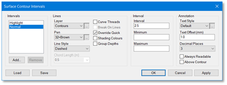
Contour Settings
The colour and line style used when plotting the triangles is controlled by the DTM settings. This dialog also controls how triangles are linked, with a maximum side length and filtering of long thin triangles, along boundaries.
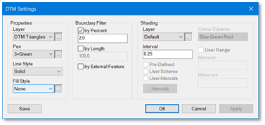
DTM Settings
The same dialog also controls Shading. This is turned on/off using the layer override [ALT+F9].
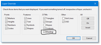
Layer Override – Shading
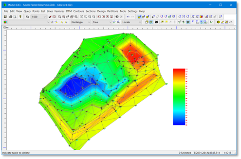
Height Shading
A height key can be plotted alongside the DTM, as shown here. This appears on CAD layer nominated, in the Dedicated CAD Backcloth and is accessed by from the Tools menu.
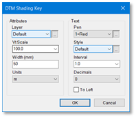
DTM Shading Key
A useful feature is the ability to view the model in 3D. This is accessed using the yellow cube icon. Various tools are available here including a hard copy plot, querying the model and creating a real time fly through. If Auto Update is active, any changes to the model during editing will be see in the 3D model.
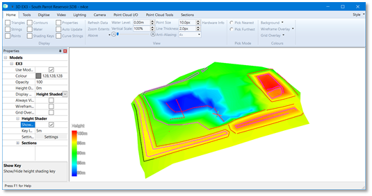
3D Viewer
You will have noted that there were two options available when creating the DTM, Normal and Unconstrained.
Sometimes models are so complex, with crossing constraints close together, that a DTM cannot be created. In situations like this its advised that long features with sparse points are densified. If this doesn’t work then you can create a DTM without forcing features, then edit manually. This is called Unconstrained.
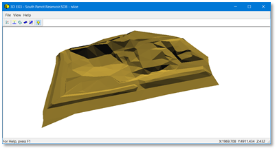
Constrained DTM
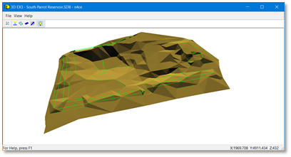
Unconstrained DTM
Note: above 3D views were created using the “old” 3D viewer, accessed by pressing the shift key during selection of the yellow cube icon.
Editing The DTM
DTM triangles can be Deleted, Inserted and Forced. Apexes forming the nodes of triangles can also be modified. Contours and text annotation of nodes will be updated accordingly, together with the 3D view, if present.
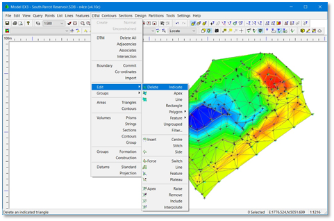
DTM Edit Menu
Boundary honouring options are not available, during the creation of a DTM. These can be post applied using one of the Delete options. If deleting triangles by rectangle or polygon, only triangles wholly within the boundary will be removed.
Once a DTM boundary has been defined, this can be saved then applied to another model. The boundary can be saved in a Co-ordinates folder and imported or copied to a new model. The delete outside this boundary feature could then be used. The delete options are self-explanatory.
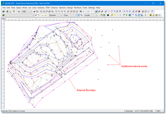
Identifying Points Outside a DTM
One of the issues with the current triangulation creation process is adding new points to an existing DTM. If new points fall within the external boundary, these can be inserted, honouring current constraints. But if they fall outside the boundary they must be stitched in manually. Alternatively, delete the DTM then reform it, with the additional points included. The latter means any previous editing will be lost!
When Inserting triangles, checks are made to avoid creating overlaps, but care must be taken. It’s possible to create holes since sides are common to adjacent triangles. Shading the triangles will visually identify holes and possibly overlapping triangles.
The forcing options are very useful as they help to remove “kinks” in the contouring, smoothing the surface. Looking at the contours and selecting the Switch option, then indicate the triangle side that passes through the contour spike. The Quick contours for the adjacent triangles will update.
Note: adjacent triangles that form a chevron will not switch as they’d create overlapping triangles.
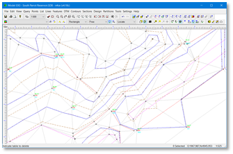
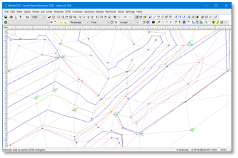
Pre-Edited Triangles Edited Triangles
Using carefully located breaklines (features) will alleviate excessive editing – but editing will still be necessary!
Along with Switching, two further editing options, called Force and Feature, help to smooth surfaces and add creases. They work in similar fashion, forcing breaklines. With the force option, you need to indicate two points which are the ends of a ridge or valley. If a feature is present, but not already included in the DTM, indicating this will force it into the DTM. Both options are useful if crossing constraints have been found and the wrong one has been applied.
Contour Plotting
The quick contours are very helpful as they update when editing the DTM, but they are segmented and will create multi elements if exported to AutoCAD. Contour defaults are set at the top of the Contour’s menu.
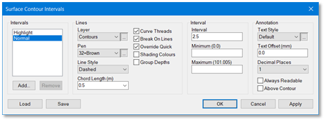
Contour Defaults
We would suggest that you use the option to Thread contours, in the Contour’s menu, to generate continuous contour lines (polylines). Options are available here to curve fit, create discontinuities (breaks) and shade contours.
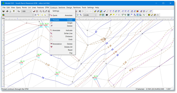
Contour Menu – Create
Threaded contours will appear in the Dedicated CAD backcloth, so you will possibly see two sets; quick contours and the threads. You need to turn the Quick contours off, using the layer override option [ALT+F9].
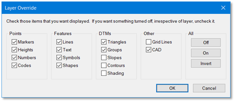
Layer Override
Further options are available with contour plotting, including Annotation.
Note: Threaded contours are NOT updated if you edit the DTM, post generation. You may have to delete threaded contours after further DTM edits then reform, otherwise they may not reflect the new model.
DTM Groups
It may be necessary to isolate different parts of your DTM; for example, a carriageway comprising of road surface, verge, footpath and banking. You may also have several spoil heaps that need identifying separately for volume quantities. This is best done using groups. Groups can have a depth which can affect contours and volume calculations so you can work to formations levels. Textures can be attached to groups for 3D viewing.
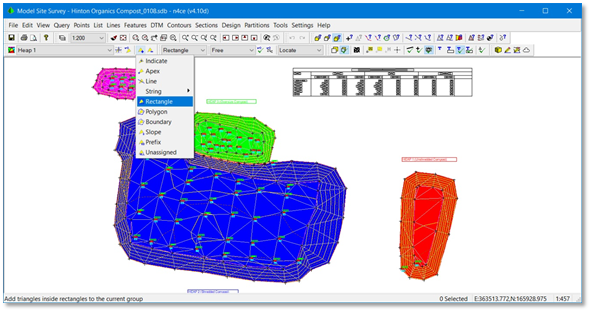
Spoil Heap Quantities – Using Groups

Groups Icon Bar
Groups are accessed using the Jesters hat icon and are selected, locked, added and removed using the 4 triangular icons. The window shows the current group (Heap 1).
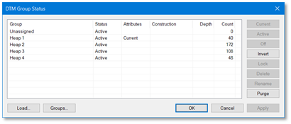
Group Status
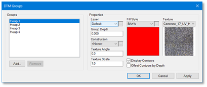
Setting Group Parameters
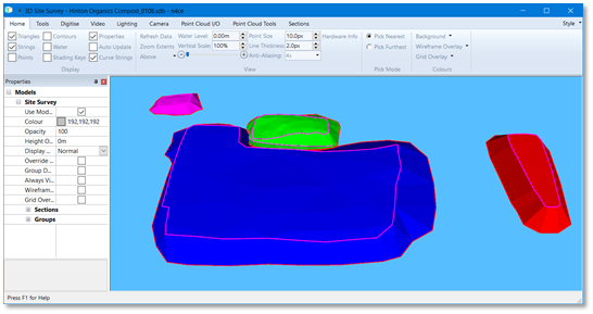
3D Viewing with Groups
Isopachytes
DTM’s we create are called a surface models and as such has no substance; sometimes called 2½ D, as you can only have one height at any location. Therefore, we must avoid overlapping triangles and can’t handle vertical faces.
When calculating volumes from DTM’s we use a containing or reference surface to encapsulate the material or void. This reference surface could be another DTM or a numerical surface, possibly calculated from sample points in the model. The height difference between the two surfaces is called an isopachyte. If created and stored as a separate model, the isopachyte can be contoured and shaded to show cut and fill.
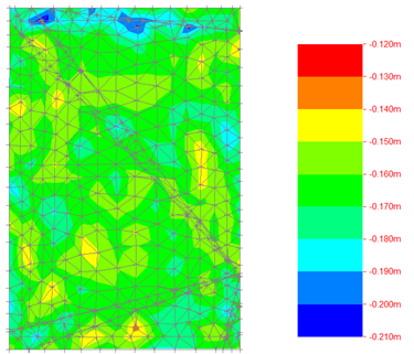
Isopachyte – Height Difference Model
Don’t forget to adjust your Shading Defaults to reflect the height differences, otherwise the image will be one solid colour!

Comments
0 comments
Please sign in to leave a comment.