
Creating DTMs
n4ce has the facility to create Digital Terrain Models (DTMs). This produces a series of non-overlapping triangles to create a continuous triangulated surface.
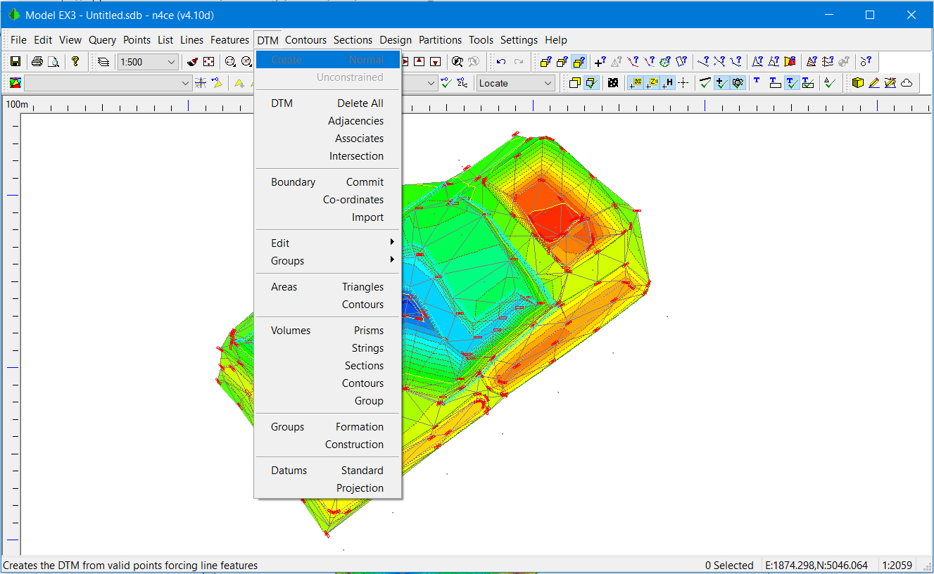
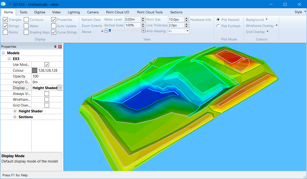
DTM Creation - Triangulated with Shading
The process used is a modified Delaunay Triangulation, with honouring of Break Lines from Coded Features. The Code Table is very important here and you may wish to review how coded points can influence the creation of DTMs.
Note The layering of Points is important here. If they are turned off they will not be used in the creation of a DTM. Likewise, if points are given a comma X or Y code then they will be eliminated from the DTM creation process.
The Triangulation process also checks for inconsistencies within the data, like duplicate points and crossing constraints. A summary of any inconsistencies found can be presented in both graphical and report form, as shown opposite.
Only coded valid points are included in the DTM. If layers are turned off that contain points, these points are ignored.
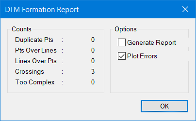
DTM Formation Summary and Reporting
Note Vertical faces CAN NOT be created in this surface model (DTM). If you wish to create the illusion of a vertical face, then offset the points from top to bottom by at least 1mm. This restriction also applies to overhangs.
Where duplicate points or overlapping constraints are found, the report identifies their location and allows you to find these inconsistencies and can be identified graphically, as shown below. These are drawn in the Dedicated CAD Backcloth on a layer called DTM Errors. It helps here if the triangles are drawn with a different colour to this error plot, as shown below.
 Access to the Dedicated CAD Backcloth is made through the View CAD Icon.
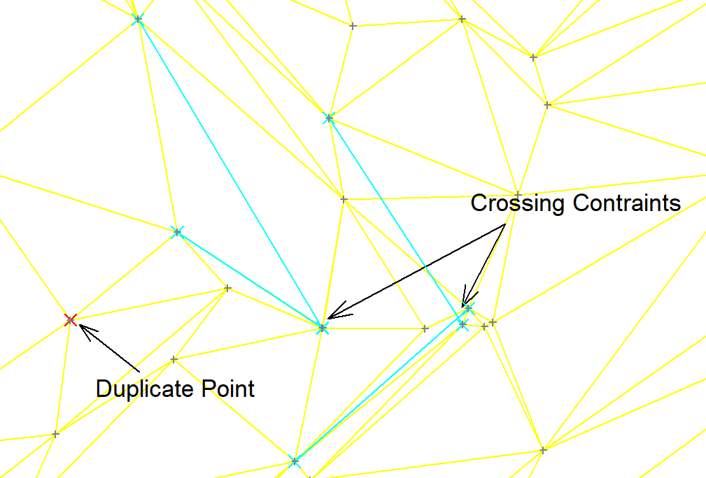
DTM Errors - Plotted
The first occurrences of a duplicate point with different levels or crossing break lines are used, so it’s up to you to edit the triangles accordingly.
During DTM creation, break lines are honoured and external triangles filtered by both length and percentage to remove long thin triangles and external concavities.
Parameters can be set and turned on/off from the DTM Setting option.
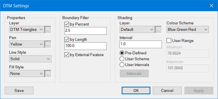
DTM Settings
This is where the Layer, Pen, Style and Shading of the Triangles are defined.
 Once the DTM has been formed, you may view this in 3D by selecting the Shaded Model Icon. Wire frame 3D views are also available.
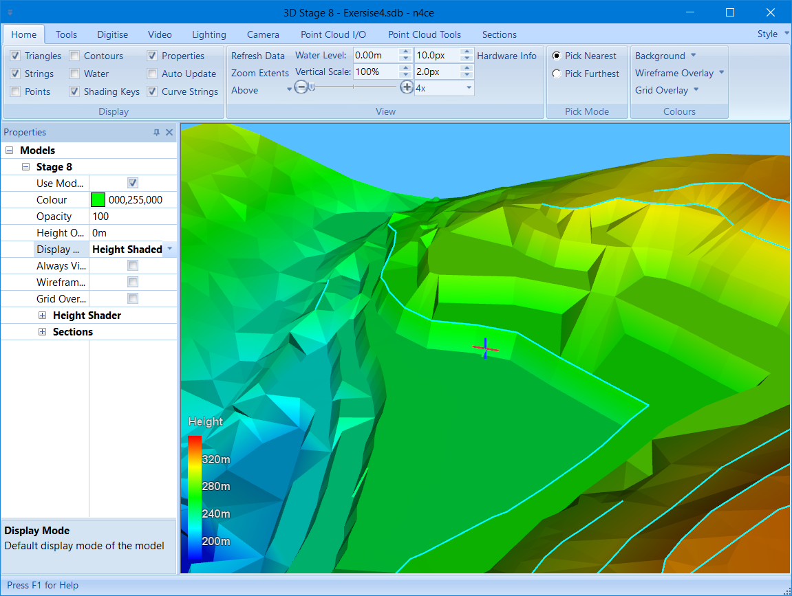
3D Shaded Model
Note There are two versions of the 3D viewer. An earlier version can be access by pressing the Shift hot key at the same time as selecting the 3D icon. The older version does not have tools for generating prints so the PrtScn button or Snippet tools should be used to generate a JPG file.
Exercise 4. Editing and Visualising DTMs
The DTM creation process forms non-overlapping triangles, considering feature constraints, called Break Lines. Whilst every effort is taken to ensure triangles are correct there are situations where they may not follow the surface features and need to be edited.
Three basic DTM editing tools are available, namely Delete, Insert and Force. In addition, Apex options allow you to Move, Delete and Include apexes in the DTM. Edits will update the DTM and contours automatically. The DTM menu, options displayed below, will vary between editions.
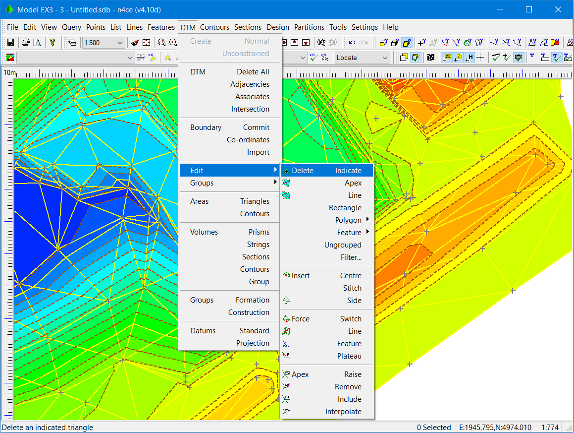
DTM Edit Menu
Note Any changes to points used within a DTM will influence the DTM itself, reforming triangles and quick contours. Care should be taken moving points as this could drag the triangles attached to that point, creating illegal overlapping triangles!
- Load the project Exercise 4.sdb located in the ..\Training folder. Once the project is loaded, highlight the model titled Stage8 and go into graphics. The display should look like that shown overleaf.
Use the DTM Settings to change the DTM Pen to light grey. -
Press the Shaded Model Icon. This activates the 3D model viewing window, allowing you to view the model in 3D space. The DTM needs to be present to see the shaded image, but a wire frame will be created from features, if the DTM turned off or missing.
The model has four modes of movement controlled by mouse buttons.
Rotation – left mouse button
Vertical Slide – right mouse button
Pan – hold roller button down
Zoom – roller ball
If there is a backcloth attached to a model, this will also be shown in the 3D viewer. A panel called Properties controls the viewing of any model present, including shading colour, features, wireframe and on/off. A Ribbon Bar is used in place of menus seen elsewhere in n4ce. Various options are available here including exaggerating the vertical scale, showing models as transparencies, altering lighting and generating a fly-through (Pro&Des).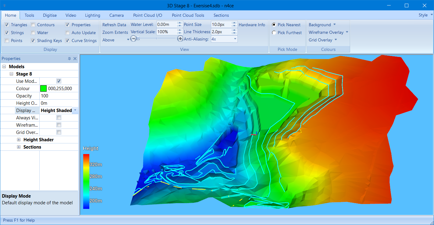
3D Viewing ControlsMultiple models, if present, will appear in the Properties panel. The Background can be set to any colour. Experiment with Display Mode. This is where you will find Height Shading, Wire Frame and Aerial Image. You can drape a geo-referenced image over your DTM.
The Vertical Scale slider bar can be used to exaggerate vertical displacements, but do not make this too large as models darken.
Height Shading uses the max/min levels to colour the model. Use the Show Key to display height differences.
The 3D model identifies several triangles that clearly cut into benches of the quarry to leave ramps. We need to remove these using the edit tools found in the DTM Edit menu.
Note The Delete All option in the DTM menu removes ALL triangles, whilst the Delete options in the Edit menu remove selected triangles -
If you do not have twin screens, a very useful Windows viewing tool called Show Windows Side by Side, in the Windows Task Bar.
This tool allows you to view multiple Windows side by side. We will use this to see changes made in plan reflected in the 3D view.
When editing the model in plan it’s possible to see the changes appearing in the 3D view. You must check Auto Upgrade in the ribbon bar first. Contours which appear once the DTM is created are called Quick Contours and will also update when editing the DTM.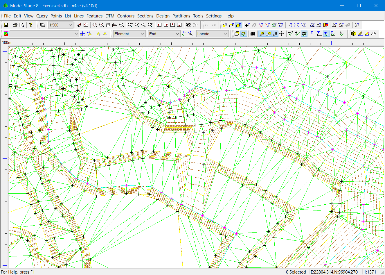
Using Force Line from the DTM Edit menu and indicate where a break line should appear between points. Triangles, contours and the 3D view will update to this new break line.
You will see contours re-drawn automatically when the triangles are edited. These on-the-fly or Quick contours are not stored in the database but are created when you zoom in or redraw the screen.
The defaults controlling contour plotting are found in the Contours menu or the Settings menu. Select this option to see the contours defaults.
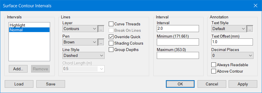
Contour Defaults
Various Intervals can be defined, with their own Min and Max limits.
Note: Each Interval has its own settings for layer, colour style, annotation offset curve fitting and breaks on lines. These also apply when committing contours to the Dedicated CAD Backcloth, as shown below.
Use the Threads Create option in the Contours menu to generate continuous strings, checking Curve Threads and Break on Lines. You will see two sets on contours, the original Quick contours and the new Curved contours.
 Curve fitted contours are created in a Dedicated CAD Backcloth as continuous strings, or polylines. This Backcloth is accessible through the Pencil Icons, providing further CAD editing tools.
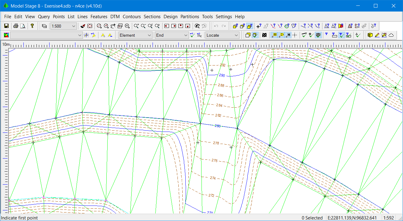
Threaded/Committed Annotated Contours
You may wish to explore the Annotate options in the Contours menu, using a Strike Line. This burns text into the CAD contours if the Offset is set to zero. Contour annotation rotates to show the direction of increasing contour value.
Note Having created threaded contours, you will have two sets of contours, one straight (on-the-fly) the other curved (CAD). To turn off the Quick Contours, use the Layers Override [ALT+F9] and turn Contours Off. Also, make a note of Grids and CAD, whilst you are here.
For curve fitted contours, if these pass over break lines you should select Break on Lines, to create discontinuities in these curves, like kerb lines.
Contour annotation will always point uphill, which is the recognised convention.
Summary of Exercise 4
This last exercise demonstrated the n4ce DTM editing and visualisation tools.
You were shown how to Force constraints, Switch triangles and Add/Remove vertexes. Whilst at the same time, see our changes effected in real-time using the 3D viewing window.
Combining these two modes of editing, helps illustrate n4ce’s tools and abilities, demonstrating how easy it is to manipulate information in 3D, and yet still provide a simple and intuitive interface.
Differences between Quick and Committed contours were identified and turning off the Quick contours with Layer Override.
The 3D viewing tools were also demonstrated.
Comments
0 comments
Please sign in to leave a comment.