
Following on from Case Study 9, which looked at the impact of flooding on a new development site, in this case study we will look at the same site and model the proposed buildings and road layout, then carry out a 3D fly-through.
Proposed Development Site
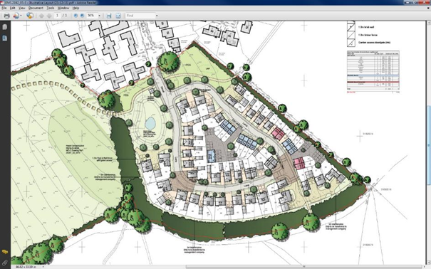
Here we will be using the proposed levels that were modelled in Case Study 9 with superimposed footpaths, roads, hard standings and buildings. These have been modelled and grouped so can be identified with different colours and of course used in any calculations for areas and volumes. The image above needs to be registered to the site coordinates. Thankfully, the builder has provided annotated grid lines that we can use for this purpose. Use the Transform option in the Tools menu (model or CAD) with the image imported as a backcloth.
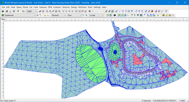
Proposed Site Levels Modelled and Grouped
The individual buildings can now be modelled and superimposed onto this model, to create a 3D view as shown below. The existing properties to the north and east were surveyed and modelled separately and are shown here in grey.
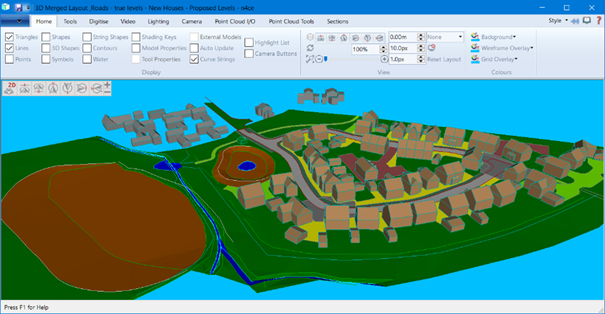
3D Model of Proposed Development Site
So how did we create the above 3D image? Well, the starting point was to model the individual buildings. This information is available in a housing pack supplied by the developer. Sizing can be extracted and a little artistic licence applied!
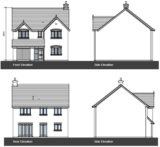
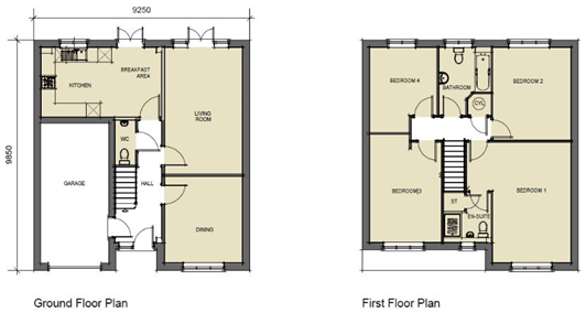
Typical House Details
There are a number of routes to creating models for 3D visualisation in n4ce, but what must be remembered is that our modelling is 2 ½ D. You can’t have vertical faces or overhangs. This means there can only be one height value at an XY position. There is no substance or solidity.
Secondly, whilst n4ce’s databases are 3D, interaction is through a 2D interface. Height values have to be added manually or calculated from a reference surface.
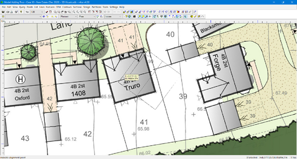
Tools provided in the modelling part of n4ce should be sufficient to create feature lines and hence planes like walls and roofs but can be assisted using CAD tools. n4ce benefits from integration and using overlays, with “look through” and locking. An example is shown below when defining the dormer windows above the roof.
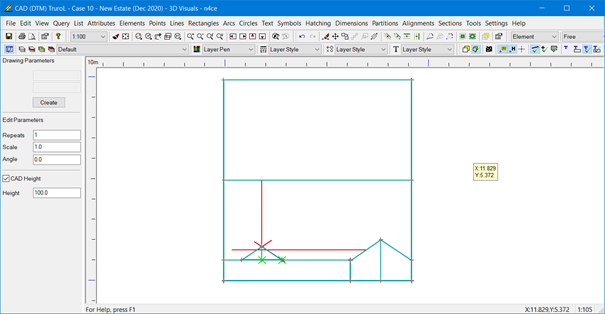
Interaction with the Dedicated CAD Backcloth
The red construction lines shown here were drawn in the Dedicated CAD Backcloth to help locate roof points in the model. When drawing features in the model use locking tools that can snap to CAD detail.
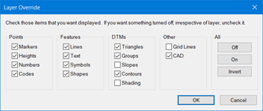
Layer Override Showing Dedicated CAD Backcloth [ALT+F9]
Note its essential that a gap is left between the top and bottom strings of a wall. 1mm would suffice, but make sure the top string is offset inwards. Next, it's important that feature starts/ends do not sit directly below/above other feature lines. The modelling process would flag a potential inconsistency, remembering it’s a 2D linking process NOT 3D!
Plan View of none-Overplaping Features – Note the Gap between Top and Bottom Wall Strings (Horizontal)
Here is the completed house shown as a model shown in plan.
House Plan
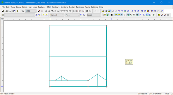
Another useful tool is the Elevation option found in the Transformation menu, allowing you to carry out further edited. Once completed the view can be returned back to plan using the Reverse option and another elevation selected. If you were really interested, doors and windows could be created and shaded using a group (after modelling).
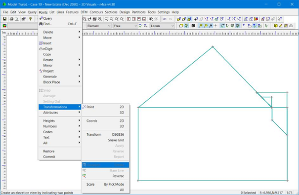
Building Elevation
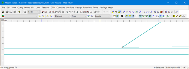
We are in a position to view the completed building using the 3D viewer. Both wireframe and shaded model are possible if the latter has a DTM created
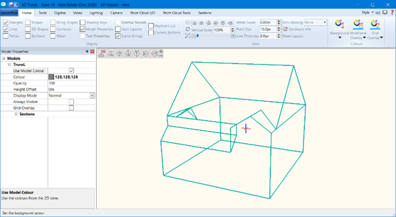
Wire Frame 3D View
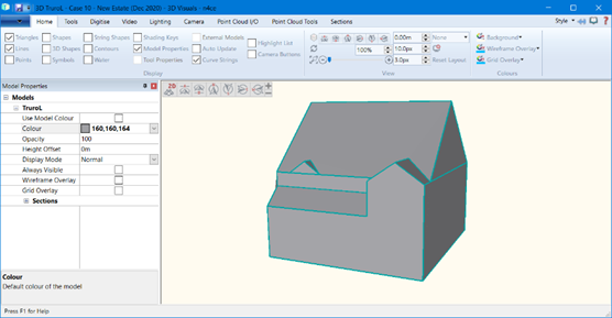
Model 3D View
The next phase is to create a Block, but first, all the points you wish to use must be added to a List, then select the To Block option, as shown below.
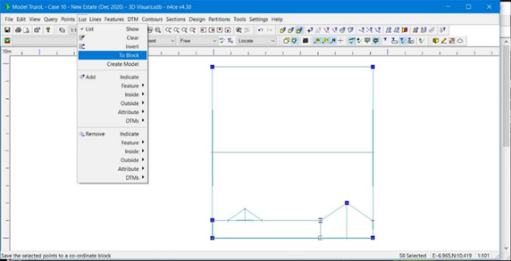
Creating a Block from Listed Points
You will be asked to identify an origin, followed by a second point which is used to orientate the Block.
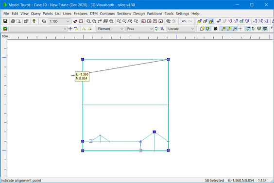
Block Definition of Origin and Orientation
Once created all the Blocks (buildings) are stored as Coordinate folders as shown here.
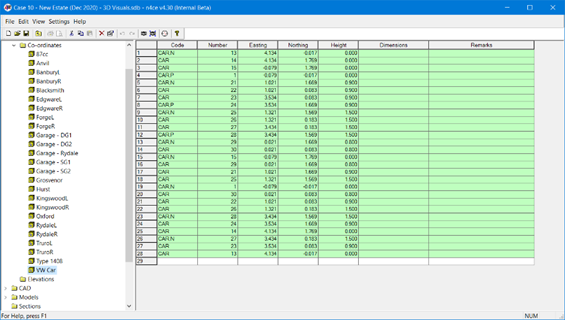
Recorded House Types and Garages (Blocks) in Coordinate Folders
House types and garages are identified on the general layout plan, so the next phase is to locate each modelled house in its correct position. n4ce has a tool that allows you to add a Block to another model, using 1pnt, 2pnt or 3pnt orientation.
In addition to adding a Block to a model, its level can be assigned or dropped onto a reference surface. This will be ideal for this project, as we want buildings to be placed on the proposed surface.
Note To make things more structured we will create a new model with just the buildings present, then combine this as a backcloth with the proposed surface (DTM) and imagery from the general layout.
When placing a Block, you will be asked to select one from a list, as shown here. Each building and garage was given its own name.
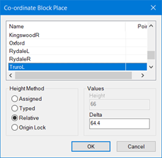
Selecting a Block to Place
The layout image is useful here to locate each building in plan correctly. After defining the origin, a rubber-banded line can be used to fix the orientation. An outline of the Block will be shown in plan.
Block Place – Outline Shown
We can now look at the placement of the building either as a wireframe or solid (DTM) as shown here in 3D. The layout imagery is sitting on the proposed final design levels.
First Building Planted on the Proposed Building Layout
After adding all the Blocks representing new house and garages we’re in a position to generate a DTM for the proposed buildings. But before we do, and to save some time editing, it may be work changing the DTM Settings to link points with a distance of less than 5m, otherwise an unwanted triangle will appear. We wish to see individual buildings modelled.
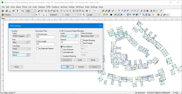
DTM Settings – 5m Spaced Triangle Sides
Even though we restricted triangle sides to less than 5m we will still get linkage to adjacent buildings, but the long across site triangles are missing. Use the DTM Editing tools to strike line delete unwanted triangles. Viewing the plan and in 3D during editing may help here.
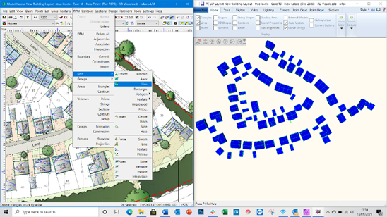
Twin Screen Viewing and editing
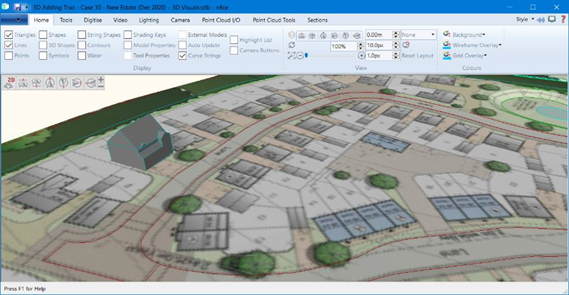
The proposed buildings, ground model and imagery can be brought together using backcloths and viewed in 3D. You can play around with colours, as shown here.
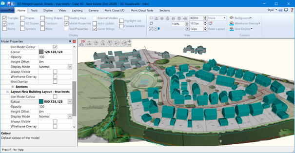
Final 3D Visualisation of the Proposed Development
But the story doesn’t end here as we’d like to see a fly-through. In the 3D viewer select the Video tab, setting the offset height to 1.5m then pick points along the proposed alignment.
4 icons control viewing, including creating a real-time video in MP4 format.
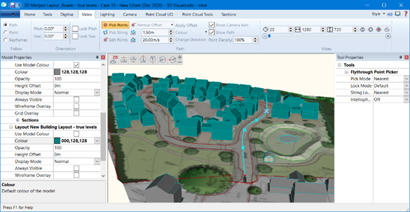
Defining a Flight Path
A still of the fly-through is shown here, indicating a line representing the flight path. You can alter the speed and other parameters of the flight.
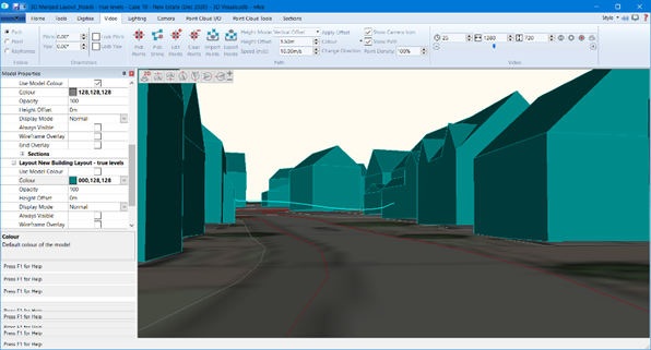
Flightpath
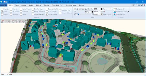
Another issue being investigated was clear access to the estate, especially for emergency vehicles as parked vehicles may be a problem. We modelled a make-believe car (VW Golf?) and placed it close to properties in typical on-street parking. These are shown in yellow, red and blue below. There are tools in the 3D viewer for querying distances.
Simulating On-Street Parking
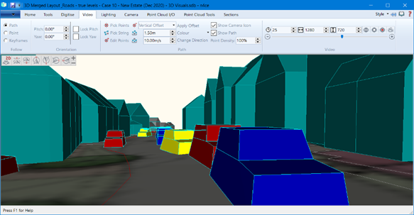
On-Street Parking Showing Possible Obstruction to Emergency Vehicles
This project shows off some of the powerful tools currently available in n4ce. New modelling tools will be available post v4.30 that will allow full 3D modelling.
The only problem is you will need to buy/create these models beforehand outside of n4ce. We plan to have street furniture models available as standard. Then this is what you may be able to create…
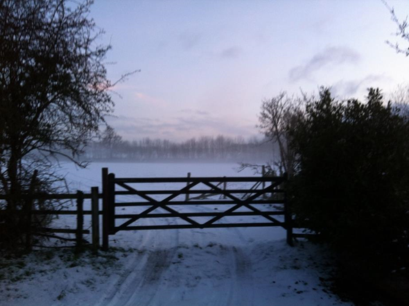
Before Build
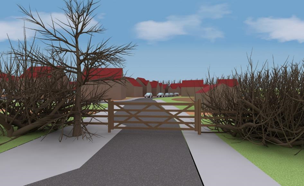
After Build
Comments
0 comments
Please sign in to leave a comment.