Links for the needed files: https://www.dropbox.com/s/jb44s54w4oqm6p8/Case%205%20-%20Hydrographic%20Survey%20%28May%202020%29.sdb?dl=0
AiC produces tablet-based software for data collection from various devices including GNNS and total stations. Whilst these programs have their own features, they do not include modelling or design. Data needs to be exported from these programs and imported into n4ce.
Here we will look at 4Site Sonar data captured using a total station and a Sonarmite echo sounder. Data from these devices are time-stamped allowing the real-time positioning and bed profiles to be identified, as shown below.

The site use here was at the inlet to yacht mooring on Lough Neagh in Northern Ireland, which had to be kept clear with a 1.2m draft. In the past, the rivers department took out a rowing boat with a dipping stick to identify silt build up. Although this is an inland lough it is sufficiently large to be tidal, with stream flows moving sediment.

The sonar data and total station data was merged within the 4Site Sonar software and exported into n4ce using an .EXP file format. The data from 4Site Sonar can be pre-processed to remove spikes and poor quality data due to the reflected signal from the Sonarmite.

Hydrographic Data Imported into n4ce
For the purpose of this survey, we will give the setup station A coordinates of 1000, 1000,100 and use a RO sighting to an arbitrary station for reduction (see above -88 point number and zero distance). If fixed points were known then real control values would have been used.
After reduction, create a new model called Lough Neagh using the survey data supplied, then form a DTM. You should see the following when viewing this model graphically.

Hydrographic Survey with Contours Spacing (0.1m Brown and 1.0m Blue)
Height shading can be turned on using ALT+F9 and shading intervals and colours in DTM Settings. Here we are using 0.5 intervals with Blue, Green & Red.

Hydrographic Survey Data with 5.1m Clearance Plane.
The 3D model of the data is shown above with a plane representing the freeboard required for boats to navigate through the channel.
The exercise here is to dredge the channel to this bed depth of 5.1m for a width of 20m. The designed channel we create will be marked by buoys.
Whilst we can use the survey data as is, we’re going to simplify the model by generating a 5m grid and use this grid as the basis for the design. Right-click over Models and generate a filename called Lough Neagh 5m Grid. Create the DTM for this model as shown below.

Forming a 5m Grid Model

Forming a 5m Grid Model
The contour intervals for the model should be set to Normal 0.1m and Highlight 1m. These contours will be used to lay down a centre line for the channel passage.
Create an empty model called Channel, then add the Grid model as a backcloth. Using Point --> Insert and the contours that indicate the slopes of the existing channel lay down a centreline with a code CL and a constant height of 5.1m, as shown below.

Insert Points to CL at a fixed height of 5.1m
We need to define a trapezoidal channel profile, 20m wide with a bed level of 5.1m. This could be done by sweeping out a pre-define Template, but here we will use a simple solution defining each string separately. Using Lines-->Parallel create parallel 10m offsets from the centreline with a code BB.
We are now able to use these offset strings to generate a batter up to the existing bed profile, but before we do it's always useful to have a close spacing on points especially on long segments. We will use the Lines-->Densify-->All option to generate additional points along all strings at 5m spacing. In hindsight, we should have done this before generating the parallel offsets. It’s always good to think ahead!
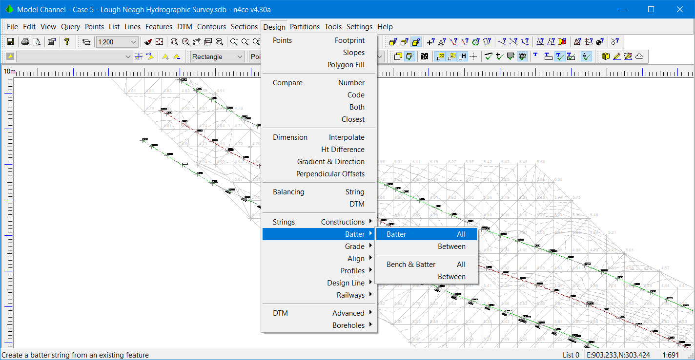
Choose the option Design Strings Batter All to generate batter slopes from the design to intercept the 5m grid model. Set the Up Batter Slope to 1 in 5, with a TB String Code and the Reference DTM to Lough Neagh 5m Grid.

Setting Batter String Parameters

Selecting Batter Options
Note there are separate options for battering up, down or both together. Here we will choose the up option. The reference surface can be another DTM, a Datum or a height change. If all three are set the batter will stop at the first condition it satisfies. The batter extent should be set to 100%. If you are battering a feature with re-entrant corners this may cause cusps which can be automatically removed. Likewise, when working with external corners a fan angle allows smoothing of batter strings.
Since the top parallel offset string sits above the reference DTM, no batter intercept will be found.
Now form the DTM for the designed channel and view it with the 5m grid as a backcloth. It should look like this when viewed in 3D.

Final Design of the Channel
Viewing the Channel and 5m grid models in 3D we clearly see that there is material to be removed to the left of the centre line. The next task is to identify how much needs removing and then provide the boundary lines for locating the buoys, indicating the extents of the channel.

Prism Volumes Using a Projected Surface and Swap Cut & Fill
With the Channel model on the screen select DTM Volumes Prisms. Since we have the final design on the screen we should check the Swap Cut & Fill to get the correct sign convention, remembering that our convention is:
“What do we have to do to the current model to make it become the Reference”
The reference here is the existing bed profile, the 5m Grid model. You will be asked to identify the reference surface, as shown here. Select the Lough Neagh 5m Grid model.

Selecting the Reference Surface for Prism Volume Calculations
A Report in a rich text editor format will be presented together with a table that can be plotted graphically. Here we will present the results from the Report.

Reporting on Volume Calculations – Note Swapped Quantities
Here we are only interested in the Cut quantity. It is suggesting that 515m3 has to be dredged out of the channel to give the freeboard required.
Setting Out Coordinates
The next exercise is to generate coordinates for the location of buoys, indicating the extents of the channel. We could provide all of the points along the parallels we created at 5m intervals but this would be excessive. We only need them at 50m spacing.
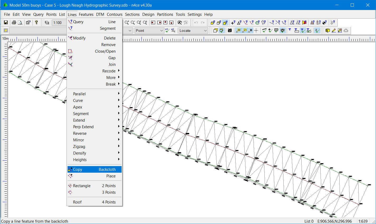
Firstly, create a new model called 50m Buoys and add the Channel model as a backcloth. Using Lines-->Copy Backcloth select both parallels forming the extents of the channel. Turn off the backcloth just leaving the two new strings on the screen.

Lines, Copy from Channel Backcloth
There are two options we can use to generate the 50m spaced points. Design-->String-->Construction-->Replace will replace the existing points with new points at the spacings indicated. These new points are linearly interpolated from original points along the line of the existing feature.
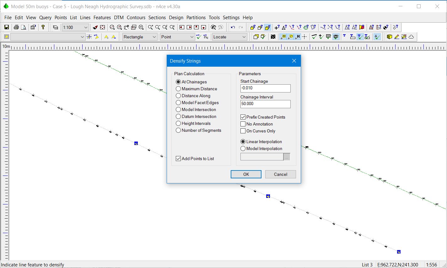
The second option uses the Densify option in the Lines menu. We used this earlier to generate additional points at 5m spacing. This time we will use the same option but add points to the List. This is an extremely powerful option and is used in conjunction with the Pick mode.
Setting the Start Chainage to -0.01 and the Chainage Interval at 50m will generate 3 new points. The start chainage was set here to -0.01 so as not to conflict with the points previously generated at 5m intervals. Listed points will be identified with a blob, as shown below.

Densify to Generate Points at 50m spacing
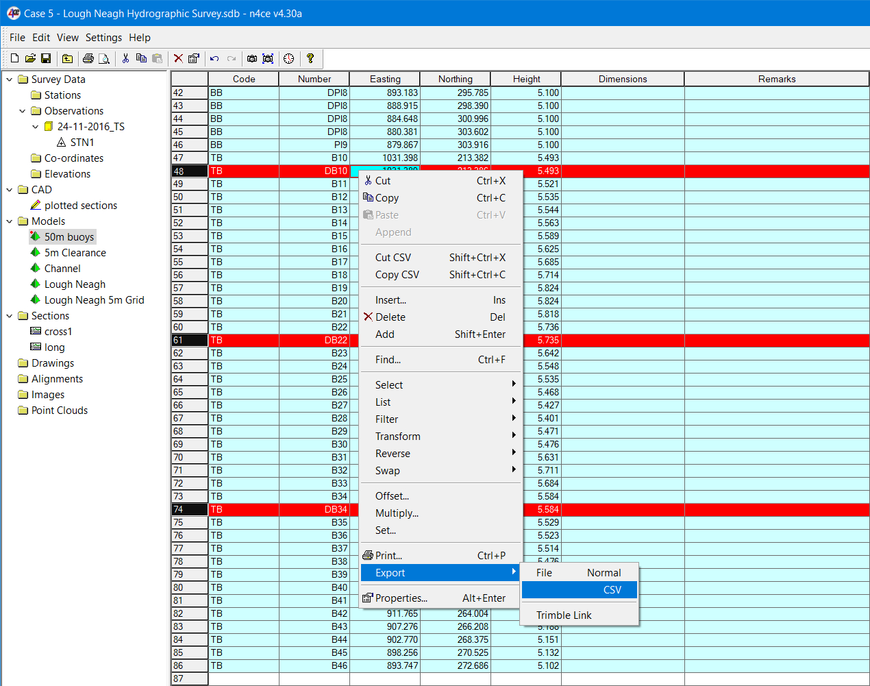
The Export CSV option can now be used in the Model Grid (spreadsheet), creating an export filter if necessary. You will have to select listed points first turning the listed points from a turquoise background colour to red, as shown here, then use the Export option.

Exporting Listed Points from the Model Grid
Note an alternative solution to finding 50m spacing points is to use the Lines-->More-->Replace option. This replaces the original points in a line feature with points at the new spacing.
Summary of Case Study 3
Quite a few powerful tools were introduced here showing the flexibility of n4ce in its role as a “Geomatics Software Tool Box”!
We started by introducing you to the 4Site Sonar data capture product used in hydrographic surveys. Data from this package was then processed into a model in n4ce and a clearance channel was designed allowing boats to enter and leave their moorings with a clear freeboard. The position of buoys markers at 50m spacing was also established. The Sonar Boat could be directed to these positions - in real-time.

Comments
0 comments
Please sign in to leave a comment.