Links for the needed files: https://www.dropbox.com/s/lxk2am2ykaidy22/Case%204%20-%20Big%20Hill%20Volume%20%28May%202020%29.sdb?dl=0
A survey was done to establish the volume of a large mound on a hillside, but there are no features that we could use to identify its base. This is required to provide the reference surface for volume calculations. The original case study looked at using DTM groups to identify the mound, but there is now an alternative solution. Read on to see how…
The starting point is a survey that has already been processed to generate a series of point coordinates. Ideally, feature strings would have been preferred, creating break lines in the DTM and nice sharp edges, but we are dealing here with only spot levels.

OGL Survey Data
Creating an OGL Model
The first stage is to generate a model from the coordinates stored in the reduced survey. Right-click over the Models folder and select New Normal, calling the new data folder Mound using a scale of 200. In the Survey tab move East Side Reclaim from the Available to Selected windows.

Creating a Model from Survey Data
Double click on the new model folder to take you into graphics. Alternatively, with the new model highlighted, select one of the camera icons.
Once in graphics select the DTM Create Normal option to form a DTM with contours. The intervals for these Quick Contours are defined in the Contours Setting menu and will update automatically when you edit the DTM. Now select the yellow cube icon to take you into the 3D viewer, as shown below.
We are interested in identifying the base of the mound that appears at the lower centre of the survey. Contours could be used to sketch out a base string, but this would only really work if the mound fell on a horizontal plane.

Mound Cleary Identified by Close Contours
Note When carrying out a survey, it's good practice to walk along with coding features and try and identify edges of planes. This is only possible if these features are clearly defined but there may be heavy vegetation or other objects that may prevent this.

Exaggerated 3D Wire Frame View of the Mound Showing Creases
From the 3D view, it’s possible to identify the base of the mound, as a crease. This view can be exaggerated by increasing the vertical scale. Tools are available in the Digitise tab to sketch features in the 3D view and see them appear in the model plan view. These tools were developed for our Point Clouds solutions available in Pro&Des. editions

Digitise options in the 3D Viewer with Model Height Shading
- Turn on Points in the 3D viewer. If it helps, also turn on Height Shading. Now exaggerate the vertical scale using the slider bar.
- From the Digitise tab, Set the feature code to BB, select New followed by Select Points and start picking up points around the base of the mound. You can still move around the mound during digitising to get to all areas. Right-click when complete.
- You will now have a feature string in the model called BB. Returning back to the model plan view, turn off the triangles and contours using (ALT+F9) to reveal the digitised feature. If necessary use the Lines editing tools to break and remove overlaps and join if necessary. We need one continuous closed feature.
- At some point, we need to copy this string to a new model so it can be used to create a reference surface. This is possibly best done from the model grid (spreadsheet). Create a new model, calling it Base String and copy and paste the BB string into this new model.

Copying the Feature String BB
As they say, “There are more ways to skin a cat” and it’s the case when using n4ce. So let’s explore some of the options we have here when calculating volumes.
Option 1 – use the boundary to encapsulate the mound triangles.

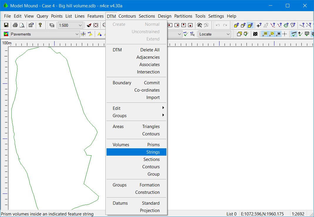
DTM Menu with Volumes using Strings
In this option, all the triangles that fall within this boundary will be used to calculate the volume. Ideally, the boundary string should be part of the DTM. In the Pro&Des editions, it’s possible to stitch this string feature into the DTM. Here we will use it as found.

Selecting a Reference Surface
We have a choice of the reference surface, as identified here. If we use one of the top 4 options, this creates the best fit surface from points found in the boundary string.

Report on String Volumes
We will use an Inclined Plane. This gives a material vol of 395,090cu m and void vol 2,330cu m and a balance of 392,760cu m. Clearly, the base of the heap is undulating and an Inclined plane is too much of a simplification, but we have usable quantities very quickly.
Option 2 – use the boundary in the Base String model to create a reference surface
Firstly, form a DTM with the Base String model. This will be used as the reference surface for volume calculations. If necessary used the DTM Editing tools to remove triangles filling boundaries.
In this method, we are going to project the Mound model down to the Base String model. It can, of course, be done the other way round, switching quantities.

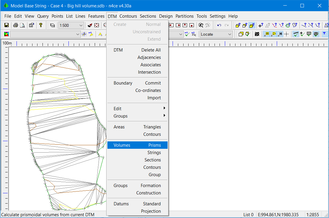
DTM Menu with Volumes using Prisms
Height differences between each model, at triangle modes, are calculated and where triangle sides from one model cross the other model additional height difference points are identified.
From these new points, n4ce creates a temporary height difference multifaceted model called an isopachyte and uses this to very accurately calculate volumes between two DTM models.
Only common overlapping areas will be used in this calculation and any spikes or less dense areas will be taken into consideration.
Return back to the Mound model and select DTM Volumes Prisms.

Selecting the Projected Surface Option
You will be invited to select a reference surface as before, but note the additional options. Here we need to select Projected Surface.

Selecting the Reference Surface
You will see the outline of both the current and the reference models, in different colours. Make sure they overlap!

Results of Volumes by Prisms
With this more accurate method of calculation, the results give a cut volume of 397,769cu m and a fill vol of 437cu m with an overall balance of 397,332cu m.
Comparing the results from both methods of calculation gives a difference of 4,572cu m (397,332 - 392,760) or around 1%. To put this into context when comparing volumes between contractors, if the resulting separately calculated quantities agree to within 3% this is generally deemed acceptable – you may disagree!
Summary of Case Study 4
In this case study, we examine different ways of calculating volumes from a survey where feature strings have not been used. In the process, the 3D viewer is used to identify the triangles that are of interest.
When displaying results, you will be given the option to plot a table. This will be drawn in the dedicated CAD backcloth for that model. A report, as shown above, can be printed, saved or parts copied and pasted into a Word document.

Comments
0 comments
Please sign in to leave a comment.