Links for the needed files: https://www.dropbox.com/s/yd9wa6e8lot6vxp/Case%203%20-%20Generating%20Points%20From%20CAD%20%28May%202020%29.sdb?dl=0
Since AutoCAD DWG/DXF are common currency in our business, one of the issues you may be faced with is generating points from CAD so that they can be modelled. You may be required to create points for setting out, or for generating volumes given the design or simply to agree on muck shift quantities with a third party. This is a non-trivial exercise and time should be given to filter out the correct information, without data overload! If you are lucky this will already be in 3D so the process will be simplified, but it’s more likely that the information provided will be in 2D.

The Topo Provided in DX/DWG File Format
Creating an OGL Model
The first stage will be to import the CAD data and generate points that can be used in a model to form a DTM. In this case, the Topo3D is already in 3D, as seen above. The Y in the last column indicates CAD elements on his layer could be three dimensions.
There are multiple layers in the Topo3D survey, some of which contain detail generated from survey points, which could create duplicate data. Further, there may be detail which is above or below the ground profile that needs to be filtered out and ignored. By observing each layer name and the number of elements on each layer, it should be possible to identify survey points and hard line features like kerbs, buildings and banking. View these layers independently then turn off the layers you don’t need. The remaining active layers will form the basis of the original ground levels.
Firstly identify the layers:
BOTTOM_OF_BANK
FOOTPATH
KERB
LEVELS
OBS_MARKER
SPOT_LEVEL
TOP_OF_BANK
For this exercise, we are going to copy these layers to another empty CAD folder. This is not essential as you could leave them where they are. But, if you return to this exercise at some time in the future and have modified the original data folders it will be difficult to complete this exercise. Highlight and copy these layers to a new CAD folder called OGL – Extracted Copy.
The process we are going to use is called Generating points from CAD, but other tools could be used that are available in the Insert option from the same Points menu.

CAD data folder OGL - Extracted Copy with Selected Layers
To make life a little easier we are going to rename the layers to the names used in the code in the Code Table, as follows:
BOTTOM_OF_BANK BB
KERB KB
TOP_OF_BANK TB
FENCE_(B_W) FEB
FOOTPATH FP
This will allow us to automatically generate line features using the layer name as the feature code. Turn off all the other layers apart from the above.

Selecting Active Layers for Point Generation
Now create a new model called OGL and add as a backcloth the CAD folder called OGL – Extracted Copy. Use the left Backcloth icon ![]() .
.
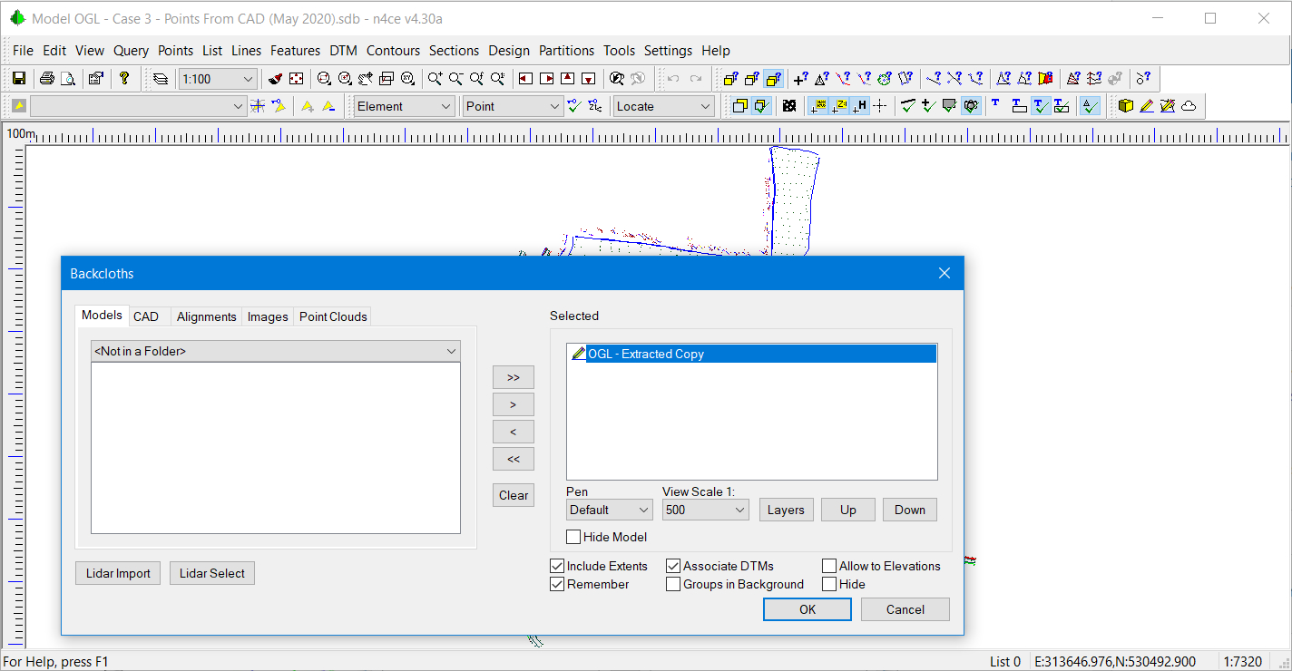
Model OGL with the CAD Backcloth OGL – Extracted Copy
Since the Codes BB, TB, FP, FEB and KB exist in the Code Table we can now generate points directly from the renamed CAD layers using the Points Generate option.
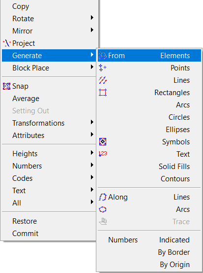
Generate from CAD

Generating Points from Elements
There are a number of options to generate points from CAD elements including from Points, Lines, Rectangles etc. A particularly useful one is from Text. This will generate a point at the origin of the text and take the numerical value from the text itself for the height of the point. Also, note the options from Contours and along lines and arcs. Points along lines can be filtered to reduce density.
The option from Elements will be used here, taking any CAD element type. It just so happens that we will be using line elements for BB, TB and KB.
Use the Assigned option for Height Calculation. This will take the level from the 3D CAD element, which we know is 3D. From Options, enable the Layer is Code, Check for Duplicates and Trace lines. Sometimes lines that may appear continuous (polylines) are drawn as segments. The Trace option will link these together to generate polylines. You may also apply a Tolerance check, but we’ll leave this unchecked here, so an automatic tolerance of 0.05mm will apply.
The Maximum Spacing can be set to zero. This will only add points at the ends of line segments otherwise, additional points will be interpolated along line segments at the spacing indicated. Also, select N to identify each new string. Use Rectangle Pick to select elements.

3D View of Extracted Features
Going back to the original CAD folder, three layers appear to contain survey points. These are LEVELS, OBS_MARKER and SPOT_LEVEL. If you view OGL – Extracted Copy in the CAD editor and use Element Show on one of the points you will see that it’s a symbol with a valid height. Text items on these layers confirm that the heights are correct. Make LEVELS the Current layer and the other two layers containing points Active. All other layers should be turned off.

Selecting CAD Layers with Point Detail
Return back to the OGL model and view the CAD backcloth with just model features turned on (ALT+F9), as identified below. Spaces between features are now identified with CAD points.

Adding the CAD Backcloth to a Model with Just Features Displayed
We will use the Generate from points option again, but this time select from Symbols. The dialogue box, shown below will now appear.

Generate Points from CAD Symbols
This time select Assigned for Height Calculation, SL for the point Code, None for String Numbers. Also, check Check Duplicates as points previously generated for line features may already be present. The Layer Code should be unchecked.
Press OK then sweep out a rectangle encapsulating the CAD symbol points. Turn off the CAD backcloth and generate a DTM, accepting reporting. You should see the following images. Note the spikes!

3D Model of Points Generated from CAD – with Spikes!
It’s important to generate points in this order, adding the features first followed by the spot levels. The features generate break lines in the model, minimizing the need to edit the DTM, but there will always be some editing that is required. For example, an error message did appear after creating the DTM to say there were overlapping break lines.
The next stage is to edit the DTM taking out any spikes in the DTM and removing triangles filling in external boundaries. This is possibly best done with the plan and the 3D view present.
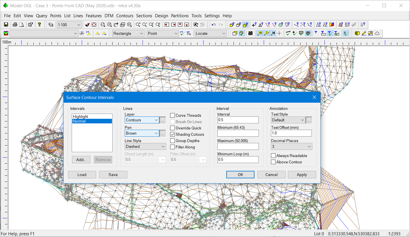
Set the Contour Intervals to see Spikes
Set Normal contour interval to 0.5m and Highlight to 5m. This will help identify the spikes in the DTM, then use the DTM Edit options, Delete by Line, Apex Remove and Switch using the contours in the plan to see where edits are required. This could be a time-consuming process!

Edit Model Removing Spikes, Switching and Deleting Triangles
We’ve been very lucky here as our CAD data is in 3D. If this was not the case much more work is required! You will need the text items that represent levels and a location. If contours are annotated these could also be used.
- The Points Insert option allows you to digitise points by indicating the position of new points and selecting an option to allocate the height.
If a CAD point (symbol) or line feature is present you can use the Locking modes to accurately locate the new point and then the Indicated Text option for height calculation. This can take a lot of time but is best used for hard line detail like kerbs, or buildings.

Point Insert Using CAD Text For Heights
- CAD text itself can be used to generate points using Points Generate. New points will appear at the insertion handle for the CAD text, typically bottom left.

Generating Points From CAD Text
- If you choose the option to generate points from Symbols there is a height calculation called Closest Text. In this case, n4ce will search for the nearest CAD text item and convert this to a height, allocating this to the new model point. Clearly, some care has to be exercised here as the level allocated may not be the right one! You can always manually edit this using Points Move Heights from Text.
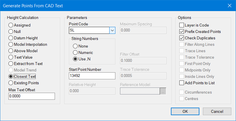
Generating Points From CAD Symbols using Nearest Text
- Finally, if all you have are contours with annotation you can use the Points Generate Contours You will be expected to indicate the contours at the same elevation followed by the text associate with this contour value.
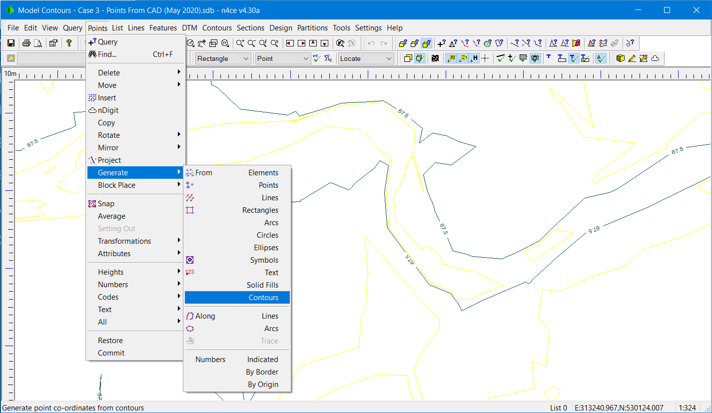
Generating Points From CAD Contour Lines
Summary of Case Study 3
This exercise investigates the different methods of generating points from CAD to create a model and hence a DTM. Backcloths are used here.
Ideally, data should be requested in 3D but this is not always possible. The quality of the resulting model will be affected by the method used.

Comments
0 comments
Please sign in to leave a comment.