Profile templates are sectional profiles that can be applied along features and alignments to create additional features running parallel to the original. The Profiles option from the Design menu allows you to create and modify profile templates and apply them. When selected, the pop-up menu to the right will be displayed.

Creating and Editing Profile Templates
The Templates Create option allows you to create and to modify templates. When selected, the Profile Templates dialog is displayed as shown to the right. The Templates list shows a list of the names of the profile templates that have already been created. When a template is highlighted in this list, a preview of the template is shown.
Templates are not stored in the current project but are stored in the n4ce Templates directory, which can be accessed using the n4ce Support shortcut that is placed on the computer desktop during installation.

The New button allows you to create a new template from scratch, the Edit button allows you to modify an existing template and the Copy button allows you to copy an existing template and then modify it. The Delete button allows you to delete the highlighted template from your computer.
When you are creating or modifying profile templates, you will be using the Profile Template dialog, shown to the right. You will be required to define the feature strings that are to be created to the left and right of the design line. The feature represented by the code at the top of each list is the closest to the design line. The appropriate Add button allows you to add a new feature to the bottom of each list. The Remove buttons allow you to remove the highlighted feature from the lists.

The Up and Down buttons allow you to move a feature string up or down each list making it either closer to or further from the design line. A preview is shown in the centre of the dialog with the Vt Exaggeration field allowing you to stretch the preview in the vertical. The Mirror buttons allow you to mirror the left to the right or vice versa. The arrows on each button define the direction of the mirror. If you use either of these buttons, any strings on the side to which a mirror is taking place will be removed.
When you add a feature string, you will be using the Profile String Parameters dialog box, shown to the right. The Code field defines the code to be used for the string, with the drop list containing all the feature code prefixes in the current project.

The Type field defines how each feature is calculated relative to the previous feature. When a type is selected from the drop list, the other items in the dialog could be enabled or disabled as required.
Some profile strings are defined at a given slope from the previous string. The Slope group defines the slope that is to be applied and the Direction field defines the direction of the slope. The format of the slope that you enter depends on which of the radio buttons is checked. If 1 in is checked, you will be expected to enter a grade whilst if the Percent is checked, you will be expected to enter a percentage gradient. The Slope field contains a drop list which gives suggested values which change depending upon which of the radio buttons is selected.
The Offset features are parallel strings that use the Offset field to define the parallel offset and are as follows.
Offset This will create a parallel string whose points will be at the same height as the points in the previous string.
Offset & Height This will create a parallel string whose points will be at a constant height above or below the points in the previous string. The change in height is defined in the Height field.
Offset & Slope This will create a parallel string whose points will slope up or down from the points in the previous string. The slope is defined in the Slope field and the direction of slope in the Direction field. Note that Up & Down is an invalid direction for this string.
When applying profile templates to an alignment, superelevation can be applied to the first and last of these types of offset string. This uses the Superelevate check button and you will have to define the design parameters when templates are applied.
The Batter strings create points that batter up or down at a given slope until the batter requirement is met. These strings use the slope parameters and are as follows.
Batter to DTM This will create a batter string that intersects with a reference DTM which will be defined when the profile template is applied. This string would normally be the last profile string in a template.
Batter to Through This will create a batter string whose points are at a given height above or below the points in the previous string. The change in heights is defined in the Height field. Note that Up & Down is an invalid direction for this string.
Batter to Datum This will create a batter string whose points are at a given datum which is defined on the Height field. Note that the direction of batter for this string is always up and down.
Profile Templates Along Features
After selecting one of the Feature options, you will have to indicate the feature to which the profile template is to be applied. If you have selected Feature Between, you will be asked to indicate the start and endpoints for the template. You will then be asked to indicate which is the right-hand side of the feature. You will then be asked to choose the template to apply using the Profile Templates dialog box and the strings will be created.

The points created for each template will copy the comma codes from the point on the reference string. Therefore, if the reference string is curve-fitted, the points created on the template are curve-fitted and, if the gap comma code is used at a reference point, the gap is also applied to the template points.
Profile Templates Along Alignments
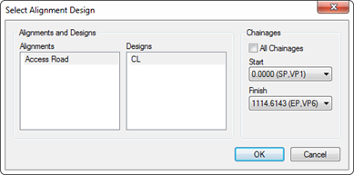
After selecting one of the Alignment options, you will be asked to select the alignment that you wish to apply the profile templates along using the dialog box to the right. If you have selected the Alignments All option, the Chainages group to the right of the dialog will not be present.
The Alignments list contain the names of the alignment models in the project. The Designs list contains the names of the designs in each model. As you select an alignment model, the list of designs will update.

The Chainages group defines the start and finish chainages for the application of templates. The All Chainages checkbox allows you to select the whole design. The Start and Finish drop lists contain the chainages at all points on the current design, some of which will contain additional information to help you identify where the various elements of the design start and finish as follows.
SP This point is the start of the alignment and will appear on the first point.
EP This point is the end of the alignment and will appear on the last point.
TP This point is a horizontal tangent point and appears where there is a change of horizontal element.
VP This point is a vertical design point and appears where there is a change in the vertical element.
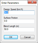
Once you have selected the alignment design, you will be asked to select the profile template to use and then to define the design parameters for the alignment using the dialog box shown to the left. The Design Speed is the speed for the superelevation calculations. Surface Friction is the lateral friction factor for the type of road surface.

Superelevation is applied along arcs and transitions and, where it takes place, there may is the possibility of sudden changes in height along with a feature. The Blend Length defines the length by which these steps are removed. Linear interpolation is used to adjust the heights of the points along the blend length so that there are no sudden changes in cross-fall.
Once these parameters have been defined, n4ce will create new features in the same way as that for applying profiles to feature strings. In this case, however, a new string will be created along the centre line using the name of the alignment design as the code for ths points.

Comments
0 comments
Please sign in to leave a comment.