The Construction options on the DTM Design menu allow you to create new features in your model. These will be created using existing features.
Haul Road Design
The Haul Road option allows you to create a feature that falls in two directions at the same time. The first direction is along the string itself whilst the second is projected out from a seeding string. After this string has been calculated, a parallel string is also created at the outer edge of the haul road. Consider the example below.
 |
 |
|
Designed Bench and Batter Surface |
Required Position of a Haul Road |
The image to the left shows a design for a bench and batter excavation and a haul road needs to be created from the last bench down to the floor of the excavation. You will be asked to indicate the point on the seeding string where the haul road is to start, point 1. You will then be asked to indicate a second point on the seeding string from which the last haul road point will be calculated. After these points have been indicated, with a check being made to ensure that they are on the same string, you will be asked to define the haul road parameters using the Haul Road Design dialog box.
The Slopes group defines the slope of both the road and the assumed batter. The Direction defines whether the haul road is being designed up or down from the seeding string. The Haul Road Slope and Batter Slope fields define the batter values to be used. These are always expressed as a grade using the 1 in X convention.

The Strings group defines further parameters relating to the feature strings that are to be created. The String Code is the code applied to the calculated haul road string and the Parallel Code is the code used for the outer edge of the haul road. The outer edge of the haul road is calculated as parallel to the haul road string using the value in the Road Width for the offset.
 |
 |
|
Creating the Haul Road Strings |
Battering the Outer Edge |
The image above shows the two strings that have been calculated. To finish the design off, the outer edge of the haul road should be battered down to the bottom of the excavation at the batter slope. You can then use the various DTM tools to edit the triangles or reform the model to use the newly created strings. When finished, the model will look like that shown to then right.

Arc Filleting Line Features
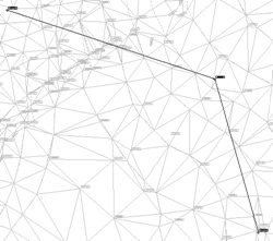
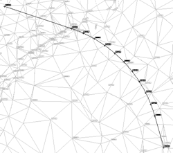
The Strings Arc Fillet option allows you to replace an apex of a line feature with one or more points defining an arc of given radius or known tangent length. This can be used in the design of site roads where a minimum radius is required for long vehicles between two constrained straights. When selected, you will be asked to indicate the feature apex to be replaced and the Fillet Arc Parameters dialog box will be displayed.

The Arc Definition group defines the plan of the arc. It can be sized by specifying a radius using the Radius field or by tangent length using the Tangent Length field. The Maximum Spacing fields defines the maximum spacing that you wish between the calculated points. If you only wish to create the tangent points, enter a value of 0.
The Heights group defines how the height of the points are calculated as follows.
Linear Interpolation The height of the two tangent points will be calculated by linear interpolation from the line feature segments either side of the indicated apex. The heights of any points created to represent the arc will be interpolated from the heights of the tangent points.
DTM Interpolation The height will be interpolated from a DTM, which can be chosen using the drop list underneath.
Null Height The points will not be assigned a height and will remain 2D.
Once you have defined the fillet arc parameters, the new points will be created.
 |
 |
|
Feature Before Arc Fillet |
Feature After Fillet Arc |

Comments
0 comments
Please sign in to leave a comment.