Levels Of Detail (LOD)
This slider controls the amount of point cloud detail displayed on the screen. The foreground is always rendered at a higher level of detail than the background, but this slider adjusts the overall percentages further. So that on PC's of lower spec the overall amount of detail can be lowered still. But on higher spec machines, more detail especially of that in the background can be displayed. The default value of 60% is usually a good starting point though for most systems.

Memory only mode tries to load the entire point cloud, plus the associated levels of detail, into memory. This can dramatically increase the performance of the point cloud. However, it can be extremely memory hungry, so should only be performed on systems with significantly more memory than the physical size of the data on disk.
Tools

- Hide/Show Points: These tools allow a selection polygon to be identified on screen to cover an area of data that is either not needed and so can be hidden. Or, to bring data back in a location where it has already been hidden. Irrespective of whether data is being hidden or shown, the selection can be either inside or outside the selected polygon.

Before Hiding

During selecting a polygon

After
- Show All Points: Resets all points in the point cloud so that they are visible again.
- Grouping: See here for more detail.
- Intensity Picker: With the display of the point cloud set to Intensity this option allows the scan to be recoloured in real-time by moving the cursor over the point data. As the intensity value is sampled the scan will change colour such that the current intensity is highlighted.
- Reset Intensity: Returns all the points in the scan to their original intensity values.
- Intensity Range: This controls the total range of intensity values being rendered either side of a value picked by the intensity picker. By default, it will be set to the total range of intensities within the current point cloud.
Transformation

Local scans are quite normal, but sometimes there is a need to move the scan into its real world coordinate system. This is accomplished via the Transform tools.
Firstly three or more data points need to be identified in the local grid scan. Ideally, these points need to be as spread out across the site as much as possible. Their real world coordinates then need to be supplied. A least squares best fit transformation can then be calculated in order to determine the best Translation and Rotation parameters needed to determine the transformation matrix.
- Select Stations: Use this button to establish at least three points in the point cloud, whose real world coordinates are also known. As each point is picked, a box will allow the station point to be identified from a list of stations loaded into the Stations folder of the Project Manager. Once at least one station has been identified, the selection list will suggest the station that has just been identified based on the distance to the station.
- Reset Transformation: Clears all current transformation information.
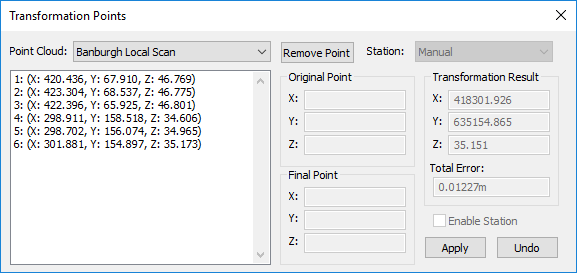
- Show Dialog: Shows a list of stations that have been identified and the results of the current transform.
- Show Stations: Toggles the display of identified stations on and off.
When enough points have been selected, right click, and the transform dialog will appear. If the resulting error is too large, individual points can be removed from the calculation by un checking their Enable Station box. When the error is within tolerance, press Apply to actually move the scan data. It can always be undone if the data needs to be localised once more.

Clipping Box

Clipping the point cloud hides data by moving the sides of a rectangular clipping box. This method is less precise at hiding data than the Hide/Show tools. However, it's much faster and easier to adjust than actually hiding point data.
Clipping options as follows...
- Enable Clipping: This button enables and disables the clipping planes in real-time.
- Edit Box: Displays a translucent box, with dots at the centre of each face will then appear around the extents of the scan. When the mouse is moved over a side, near to the black dots, the side in question will be highlighted. Once highlighted, a click and hold of the mouse, as it is dragged will move the face of the cube along its axis. As the side is moved back and forth, the scan will be clipped accordingly. Where the orientation of the scan is not aligned with the clipping box, the Rotation field in the tool strip allows the box to be reoriented to better line up with the point cloud. Once the box has been sized, click Edit Clipping Box again to deactivate its preview.
- Set Rectangle: This button changes the view to one looking down from above and allows a user definable rectangle to be drawn over an appropriate area in question. Once selected, click two points on screen first to define the longer edge and then a third to set the width of the adjacent face. The model will then be clipped to the extents of that rectangle and returned to the previous view.
- Reset Clipping Box: Resets the clipping box to that of the original extents of the point cloud.
- Rotation: Drag the slider, enter a value or use the up and down arrows to change the orientation of the clipping box. This value can also be changed when using the Set Rectangle tool.
|
No Clipping |
Right Hand Face Clipped |
Clipping box rotated |


Comments
0 comments
Please sign in to leave a comment.