Sections allow user-definable slices to be cut through one or more Point Clouds simultaneously. These slices are then viewed in a dockable window. From here is it possible to digitise floor plans or elevations from scan data?
Below is a quick example of a horizontal section cutting through the scan of a church. Next to that the resulting output from the section view.


The following explains the basic functions of the various tools in the Sections ribbon bar. More in-depth articles on how to use Sections are also available.
Display
This section controls whether or not the Section view is displayed, how it is displayed, and the background colour used in the section view.
- Section View, this toggles the display of the separate section view window. If the section view is not visible, then it may be because this option is not activated as indicated above.
- The Show Path checkbox enables or disables the preview of the green section box in the 3d View.
- Clip Main View is a useful tool to help show exactly what the section box is cutting by eliminating everything in the 3d view apart from data that intersects the section box. Below is the same as the preview above. But with the clip main view option enabled.
- All Codes Shows a string with any code in the section view.
- All Strings Shows all strings within the section view that have the same code as the one being used.
- Slice Models Show the points/Models where the sections cut through the main model/point cloud.

- Scale Bar, displays a dynamic scale bar that resizes depending on the zoom level of the section view.

The final control in the display section defines the background colour of the section window. Depending on the colour of the scan data in the view, altering the background colour (by clicking on it in the palette) can really help bring out detail that may otherwise not be clear.
Grid Overlay & Snapping

This section controls the plotting of a real-time grid over the section preview and snapping to it.
- Show Grid, enables or disables the plotting of the grid.
- Auto Grid Spacing tries to size the grid dynamically (if it's enabled) so that it is always appropriate for the current zoom level.
- Grid Spacing allows the grid interval to be set to a specific value.
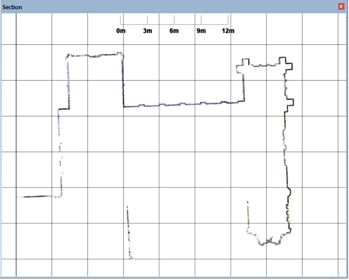 4m Grid |
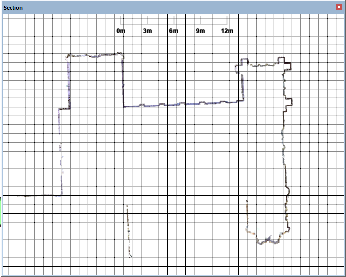 1m Grid |
- Grid Snap: enables snapping to the grid lines in the section view when ALT is pressed.
- Angle Snap: First, create a section and have the digitize tool selected. To start angle snapping hold shift and move the cursor, you will see that it jumps between regular intervals ideal for shapes with square edges. E.g. Windows.
Section

This is the administration area of the Sections ribbon.
- Reverse Section, use this option to flip the section so that it is being viewed from the opposite direction.
- Clear Section, cancels and clears the current section. Having pressed this button you will be asked if you want to keep the current section. If you press Yes the section is stored for later use, but removed from the scene. No will completely clear the section entirely.
- Delete Section, deletes a previously saved section.
- Duplicate Section, copies the current section so that the original can be preserved, and a new similar one generated.
- Sections, this box allows the current section to be given a suitable name just by overtyping the name in the box. It also, however, contains a list of any sections that have been previously saved. The default section is "Section 1", but if a section is cleared, and the user elects to save the section, a copy of the section will be added to the list.
Tools

The Tools section is where sections can be created, manipulated and exported.
- Points to Model - Transfers a copy of all the points in the section view into the current model. Ideally, this should only be done on small data sets. A simple section can still contain tens of thousands of points.
- Auto Snap - Aligns a section so that it is either perfectly vertical or horizontal, depending on which axis is it closest to.
- Align X - Creates a new section aligned perfectly to the X-Axis.

- Align Y - Creates a new section aligned perfectly to the Y-Axis.

- Align Z - Creates a new section aligned perfectly to the Z-Axis.

Note when combined with the Set Clipping Box by Rectangle tool the axis of the section is orientated to the extents of the clipping rectangle as the above examples demonstrate. - Multi Plane - Creates a section that runs perpendicularly along a route indicated by clicking points on the point cloud. The section cutting plane can then be dragged or moved to any point along that alignment represented by the black line running through the section.

- Slice Horizontal - Creates a quick 1m x1m horizontal section through the point cloud at a given location in the view. Normally this would be used to digitise small vertical objects such as tree trunks or lamp posts. If needs be, the size of the section can still be adjusted as with any normal section.

- Slice Vertical- Creates a quick 1m x1m vertical section through the point cloud at a given location in the view. Normally this would be used to digitise small horizontal objects such as Pipes or ductwork. If needs be, the size of the section can still be adjusted as with any normal section.
- Slice View - Cut a section through the view, but aligned to the direction of the camera. Having selected this tool, indicate two points in the view to set the width of the section. Having selected the second point, the section will be generated along the line of the camera's view into the scene.
- Pick Points: This method of setting up a section has three modes.
- 3 Points - A new section is defined by selecting three points in the scene. The first two points are used to define its width or height, whilst the third specifies its length. The section is aligned to the plane defined by the three selected points. If the resulting section is close to the horizontal or vertical, then a message box will appear asking if the section should be snapped to the appropriate axis. This ensures the section is perfectly horizontal or vertical if needs be.

- 2pt Diagonal Rectangle - Sets up a vertically aligned rectangular section, between two indicated points. The two points should be in diagonally opposite corners to properly define the size of the section.

- 2pt Square - Sets up a vertically aligned square section, between two indicated points. The two points should be in horizontally opposite each other along the midline of the selected square.
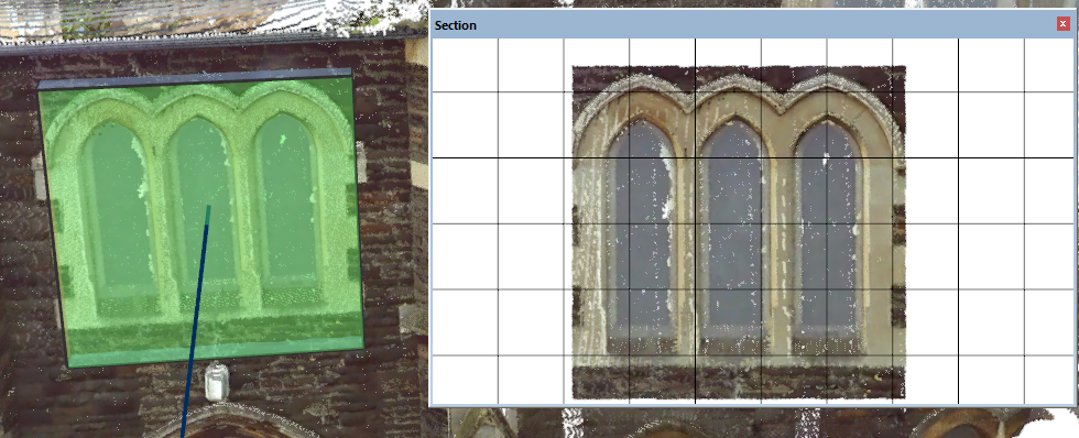
- 3 Points - A new section is defined by selecting three points in the scene. The first two points are used to define its width or height, whilst the third specifies its length. The section is aligned to the plane defined by the three selected points. If the resulting section is close to the horizontal or vertical, then a message box will appear asking if the section should be snapped to the appropriate axis. This ensures the section is perfectly horizontal or vertical if needs be.
- From Feature: This method of setting up a section has two modes.
- Feature - Select this option to section perpendicularly along the length of a selected feature. Once selected, a section will be generated at the first point of the feature aligned to the direction of the string. The section can, of course, be resized or moved to a specific place by dragging it or via the interval setting to locate the section exactly where it needs to be along the route of the feature.
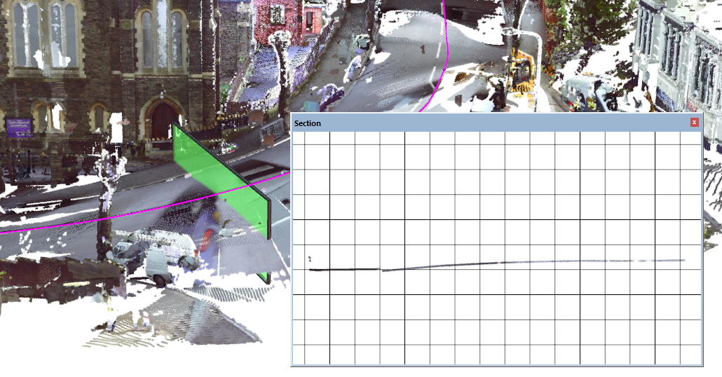
- Baseline - Snaps a section vertically using a selected segment of a feature to control the length and orientation of the section.

- Feature - Select this option to section perpendicularly along the length of a selected feature. Once selected, a section will be generated at the first point of the feature aligned to the direction of the string. The section can, of course, be resized or moved to a specific place by dragging it or via the interval setting to locate the section exactly where it needs to be along the route of the feature.
- Set Center - Relocates a section by specifying a new centre point for the section. This is useful when the same section plane is needed but in a different location. Or just to shift a section into a slightly better position.
- Zoom to Section: - Zooms the view so that the current section is zoomed and centred in the view.
- Export Geo Image: This tool makes quick 4k or 8k images from the current section. These can then be loaded back into a Model or CAD view to help to digitise detail, or to allow detail to be digitised in other 3rd party packages. The geo data stored with the image in the associated PGW file contains projection information so that when the image is imported back into n4ce it is in the correct position, or the correct height if it's an elevation image. Before the image is created a message box will ask if the current model should be flipped into the same plane as the section. This is necessary so that if the image is back-clothed to the model, the coordinate system of the model will be aligned with that of the image.
- Export Image Tool: This allows images of any size or a series of tiled images to be generated over a section. This link contains more details on custom image exports and other tools.
Elevations and Positioning a Section

- Elevation from Section: This option switches the current 2d Model view round such that it is now viewing the survey information in the model, in the same plane as that of the current section.
- Section from Elevation: If an elevation has already been generated in the current model by the Points\Transformation tools. This option will generate a section in the 3d view, but in the same plane as the elevation. This is useful when trying to take a section through a point cloud in exactly the same position as an elevation generated from survey data.
- Snap to Point: Slides an existing section along its central axis such that the plane of the section is now aligned perfectly with the indicated point. This tool is ideal when trying to be sure the plane of a section exactly cuts the intended survey detail.
- Advance: Moves the section along its central axis by the Interval value. Note Shift + < and Shift + > will also move the section backwards and forward by the Interval amount.
- Space: Switches the coordinate system between Local and World. Large national grid coordinates can sometimes be a pain to work in as the numbers are so large they can be difficult to digest. Local grid values however are constrained to the extents of the data and as such will have much smaller numbers. If however, a section needs to be taken at an exact datum, then selecting World and setting the Position value manually will ensure the section is taken in the correct place.
- Position: Specifies the location of the section along its current central axis.
- Interval: Controls by how much a section is moved along its central axis when Advance is pressed.
Sizing a Section

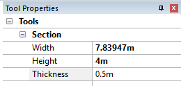
The size of the current section is controlled from either the Size section of the Sections tab. Or as and when a section is available, its settings will also be editable from the section tool properties that will be added to the right of the screen.
- Reset Size: Resizes the section to the extents of the point cloud. When combined with the Set Clipping Box by Rectangle tool this will ensure the section is no bigger than the current detail extents.
- Manual Edit: Allows a section box to be resized by pulling or pushing an appropriate side. Click and hold whilst dragging the mouse over the side to manipulate it. Remember to cancel the tool by clicking it again, otherwise, the section will change size rather than being moved when clicked on.

Comments
0 comments
Please sign in to leave a comment.