
Links
- DTM Menu
- The Contour Settings
- Contour Intervals
- Contour Ranges
- Contour Annotation
- Thread Contours
- The DTM Tools Menu
- DTM Shading Key
- DTM Group Key
- Gradient Tools
DTM Contours Menu
The Contours Menu in the DTM graphic view allows you to create the contours in the current model using the DTM triangles that have been formed. It also gives you options that create an annotation for the contours. When selected, the menu below will be displayed.
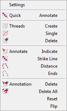
There are two types of contour which can be displayed.
Quick When a DTM is formed, contours can be automatically displayed. These are virtual contours in that no CAD information is created and they are displayed live. As the DTM is changed, the contours will automatically update themselves. These contours are a useful aid when editing a DTM and visualising the effect of the edits.
Thread After a DTM has been edited and you are happy that it represents the surface as accurately as you can make it, you may need to create thread contours if you wish to export the model to an AutoCAD DXF file. Thread contours are CAD polylines that are stored in the dedicated CAD backcloth of the current model.
The Contour Settings
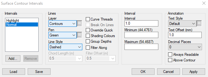
The display of both types of contour is controlled by the contours settings in the current model. These can be accessed using the Settings option. When selected, the dialog shown below will be displayed.
Contour Intervals
The Intervals list allows you to work with different contour intervals. There must an interval called Normal and when it is highlighted, you will note that the Remove button is disabled. All other intervals should be a multiple of the normal interval. Usually, a maximum of two contour intervals are required, although there are situations where three or more intervals are needed. To add an interval, select the Add button and you will be asked to enter the name of the new interval and it will be added to the list. The new contour interval will have a spacing that is the same as the interval that was highlighted before the addition. To remove an interval, press the Remove button and, after a check, the interval will be removed.
As you select each interval in the list, the remaining settings in the dialog will change accordingly. The vertical spacing of contours is defined in the Interval field. Contours lines will be displayed on the layer defined in the Layer field using the pen and line style in the Pen and Line Style fields respectively. Note that the pen and line style can be set to Layer Pen and Layer Style, respectively. In these cases, the appropriate attribute will be taken from those set for the interval layer.
When generating thread contours, you can apply curve fitting to the polylines. The Curve Threads check box allows you to specify this. If this is enabled, the Chord Length field is also enabled allowing you to specify a contour segment length. Linked to this is the Break on Lines check box. Where a thread contour crosses a line feature that has been forced into the DTM, such as a top of batter, a curve discontinuity is introduced at this point.
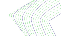
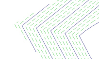
Curved Contours Curved Contours Broken Over Features
The Override Quick check box allows you to automatically turn the display of the quick contours off when thread contours are generated. If this is not carried out, it is possible that two sets of contours are displayed on the screen or two sets will be exported to an AutoCAD DXF file.
The Shading Colours check box allows you to create thread contours using the DTM shading on the current DTM. This shading is described in the previous chapter. If this check box is ticked, the colour of the contour will be interpolated from the DTM shading. Note that the DTM shading does not need to be displayed to allow this check box to be effective.
The Group Depths check box allows you to consider the depths that have been assigned to groups in the DTM. If this is checked, any triangle in a DTM group that has a depth will temporarily be dropped by the group depth before contours are calculated.
Contour Ranges
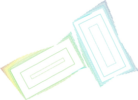
There is often the need to allow contours to be displayed at different intervals or in different colours within height bands. An example would be an isopachyte model where the negative isopachytes need to be displayed in a different colour to the positive ones. The Minimum and Maximum fields allow you to do this. Note that the minimum and maximum heights in the model are displayed as part of the title for the fields.
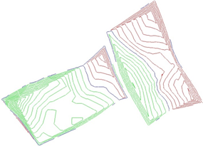
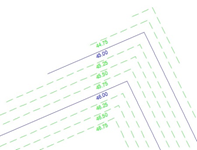
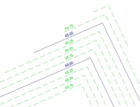
For the above example, you should set the normal interval to have height interval of, say, 1. The values in the min and max fields should both be set to 0. This would generate just a single contour at the zero isopachyte. You should then add an interval called Positive with the same height interval. The values in the min and max fields should be 1 and a suitably large value. A further interval called Negative should then be added, again with the same height interval. The values in the min and max fields should a suitably large negative value and -1. Change the colours for each interval so that they are different and the display of quick contours and generation of thread contours will be changed accordingly. In the example, positive contours are green, negative ones are red and the zero isopachyte is blue.
Contour Annotation
The Annotation group allows you to set the defaults for any contour annotation that you create. When annotation is created, it will be created on the same layer that is used to display the contour. It will also be displayed in the same pen or colour as the contour.
The Text Style field allows you to specify the text style to be used. This style can be set to “Layer Style“ in which case the text style will be taken from the contours interval’s layer. It can also be set to “None“ in which case, no contour annotation will be generated for that contour interval. The Text Offset field allows you to specify how far from a contour line the text annotation will be created. If this value is set to 0, any thread contours to which annotation is added will be gapped so that the annotation sits within the contour. The Decimal Places field controls the number of decimal places in the annotation text.
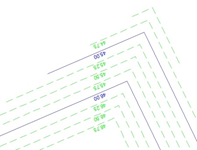
Annotation Offset from Contours Annotation Gapped into Contours
The normal convention for contour annotation in n4ce is that the text will align itself so that the top of the text points to the uphill side of the contour. Therefore, if the annotation is not inserted into the line, the whole of the text will be on the uphill side. If the annotation is inserted into the line, the top of the text will be on the uphill side. This is shown in the examples above where the text appears upside down.
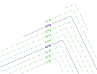
The Always Readable check box allows you to ensure that contour annotation is always readable. This means that the text can always be read from the bottom of the model so text will be positioned in the same way as above but the angle of the text may change. The Above Contour check box allows you to specify that all the annotation will be placed so that the bottom of the text is closest to the contour line. This is the default setting in n4ce but if the text is set to be always readable, this can mean that the annotation will be flipped to the other side of the contour as shown in the example below.
Annotation Always Readable Annotation Above Contours
Thread Contours
Thread contours are continuous polylines that are created by linking the individual contour elements from the triangles of the DTM. The Threads Create option allows you to create them and after it is selected, the contour settings dialog will be displayed allowing you to change any of the settings. The polylines will then be created and stored in the CAD backcloth dedicated to the current model.
The Threads Single option allows you to create a single thread contour at a user-specified value. A dialog box will be displayed asking you to specify the value together with the attributes for the contour. A single thread contour will then be created.
The Threads Delete option allows you to remove all thread contours from the dedicated CAD backcloth. All the layers that are used for contours will be searched and anything contained on those layers will be deleted. Note that the contour polylines and annotation associated with them will be deleted together with any CAD information that you have added to those layers. If the Override Quick check box is ticked, the override to turn off quick contours will be removed.
Contour Annotation
It is possible to add annotation to both the quick and thread contours. The items of annotation will be placed in the dedicated CAD backcloth on the same layer as the contours to which they refer
Annotating Quick Contours
Annotation can be added to the quick contours using the Quick Annotate option. You will be asked to indicate the start and finish of a strike line. An item of contour annotation as generated using the current contour settings where the strike line intersects any quick contour. Note that if the contour annotation offset is set to zero, the annotation will be placed within the contour but the quick contour is not broken.
Annotating Thread Contours
The Annotate options allow you to annotate any thread contours that you have created. There are four options to do this.
Indicate - This option allows you to add an item of annotation at an indicated position. You will be asked to indicate the contour to annotate. The indicated position will then be projected onto the contour to give the annotation position and orientation.
Strike Line - This option allows you to annotate contours using a user defined strike line. You will be asked to define the strike by indicating its start and end points. An item of annotation will be created where this line intersects any thread contour. You do not need to worry about which end of the strike line to indicate first as n4ce will work out the angle of the text based upon the direction of the contour.
Distance - This option allows you to add annotation along contours so that there is a maximum distance between each item of annotation. You will be asked to enter a distance in metres and the length of each contour polyline will be used to calculate the number of items of annotation to add.
Ends - This option allows you to add annotation at the end of each contour polyline. Only open-ended contours will be annotated and any closed contours will be ignored.
Editing Annotation
The Annotation options allow you to edit contour annotation.
Delete - This option allows you to delete an individual item of annotation. You will be asked to indicate it and it will be removed. Note that if the contour line to which it refers has been gapped, the gap remains.
Delete All - This option allows you to delete all contour annotation. All text on the contour layers will be removed and any gaps in contour polylines will also be removed.
Reset - This option allows you to reset any item of contour annotation to the current defaults. This may be necessary when you have created annotation with the wrong number of decimal places. The attributes that can be changed are the pen, the text style and the number of decimal places in the display.
Flip - This option allows you to rotate the contour annotation through 180°. If the annotation is offset from the contour line, it will also be moved to the other side of the contour.
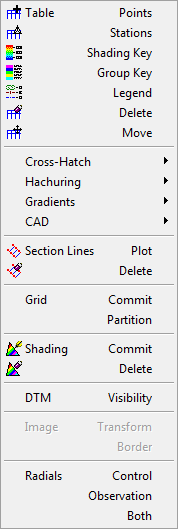
The DTM Tools Menu
The Tools Menu in the DTM graphic view gives you options that allow you to enhance the presentation of your models with such items as tables of data, cross-hatching and hachuring. It also allows you to plot section cut lines and to commit the current survey grid. All the items that are created will be added to the dedicated CAD backcloth for the current model. When selected, the menu below will be displayed.
DTM Shading Key
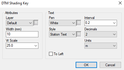
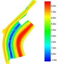
One of the n4ce settings for displaying DTM triangles is to allow the shading of triangles with different colours representing different heights. The Table Shading Key option allows you to create a key that shows the height value assigned to each colour. When selected, you will be asked to define the parameters of the key using the dialog shown below. This dialog only allows you to change the items relating to the key itself. Setting the colours used in the DTM shading has already been described.
 |
 |
|
DTM Shading Key Dialog |
Example of DTM Shading and Key |
The Layer field allows you to change the layer on which the key will be created. The Vt Scale field is used to define the vertical scale of the key. Normally, this scale should be less than the current view scale to enable a legible key to be created. You may need to use a little trial and error here to achieve the desired result. The Width field displays the width of the key in millimetres. The Units field displays the string that will be appended to each text item representing heights. The Pen and Style fields allow you to specify the attributes for the text items and the Interval field defines the interval at which you wish to generate the heights. The heights are formatted using the number of decimal places in the Decimals field.
DTM Group Key
With n4ce, you can group triangles together to highlight specific areas of a DTM using DTM groups. The Table Group Key option allows you to create a key that shows which triangles are assigned to which groups. When selected, the dialog box shown below will be displayed.
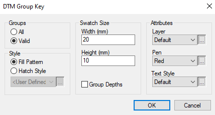
The Groups group specifies which groups to include in the key. If the All radio button is set, all the groups will be included. If the Valid radio button is set, only those groups that have one or more triangles assigned to them will be included.
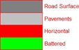
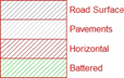
The Style group allows you to specify what you wish to appear in the swatch for each group. If Fill Pattern is set, a solid fill will be created. If Hatch Style is set, a cross-hatch using the pattern specified in the combo box will be used. In both cases, the colour used will be that of the foreground colour of the fill style assigned to the group.
The Swatch Size group specifies the size of the swatch created in the key for each group. The Width and Height fields specify the width and height of the rectangle in millimetres.
The Attributes group specifies the remaining defaults for the key. These are the layer on which it will be created, the pen used for the borders around the swatches and the text style for the group names. The pen used for the group names will be the same as that for the swatch borders.
Gradient Tools
It is often useful to be able to show the value and direction of gradients on a model. The Gradient option from the DTM Tools menu allows you to create symbols showing such gradients. When selected, the pop-up menu below will be displayed and there are four options for creation.
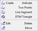
Indicate - This option will ask you to indicate any two points within the DTM triangulation. Height values will then be interpolated so that a gradient can be calculated.
Two Points - This option will display the gradient between any two points in the model. You will be asked to indicate two points. Note that points that do not have a valid height will be ignored.
Line Segment - This option will display the gradient of a line feature segment. You will be asked to indicate a feature segment and a gradient will only be displayed if the points at either end of the segment have a valid height.
DTM Triangle - This option will ask you to indicate any point within the DTM triangulation. The gradient and direction will be calculated from the indicated triangle.
Whichever of the four options is selected, the dialog box below will be displayed allowing you to specify the format of the gradient symbol.
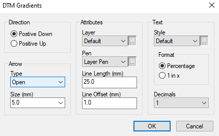
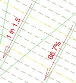
The symbol will comprise a line with an arrowhead and a piece of text showing the gradient in the direction of the line.
The Direction group allows you to define whether a positive gradient is downhill or uphill. An arrowhead will be placed on the appropriate end of the line. The arrowhead is defined by the Arrow group. The arrowhead type can be either closed, an isosceles triangle, or open, a chevron, and is defined in the Type field. The length of the arrow is defined in the Size field with the width at the base of the arrow being assumed to be 0.4 times the length. Note that the length of the arrow should be defined in millimetres.
The Attributes group contains the usual Layer and Pen fields. It also contains the Line Length field for the length of the line and the Line Offset field for the offset of the line. The latter field is only enabled if you are creating a gradient along a line feature segment or between indicated points.
The Text group defines the format of the text showing the gradient. The Style field defines the text style that is to be used and the Decimals field defines the number of decimal places in the gradient value. The Format group allows you to specify whether the text should appear as a percentage or in the 1 in xformat.
The positioning of the gradient symbol will depend upon the method of calculating the gradient. If the gradient is from a DTM triangle, the centre of the line showing the gradient direction will be at the centroid of the indicated triangle. If the gradient is calculated from either a feature line segment or two points, you will be asked which side of the two points the gradient symbol is to be positioned. The arrow line will then be offset from the line joining those two points using the Line Offset field. The text will be placed on the opposite side of the arrow line to the indicated points.
The Edit Delete option from the Gradients pop-up menu allows you to delete gradient symbols from the model. You will be asked to indicate the section lines to delete. You should ensure that you indicate an element within the hachuring. The Edit Move option allows you to move gradient symbols. You will be asked to indicate the symbol to move and then give it a new location.
Comments
0 comments
Please sign in to leave a comment.