
Text appears in n4ce graphics environment according to defaults, which include style, colour and layering.
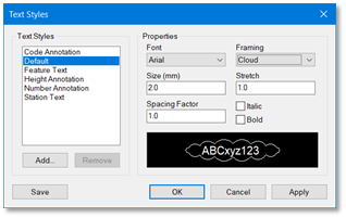
Text Styles
Each Text Style is defined in terms of Windows Font, Size (mm), line Spacing Factor, Framing and Stretch factor. Italic and Bold parameters are also available.
Text appears in mm to whatever Viewing Scale is chosen. This can be found on the Zoon icon bar.
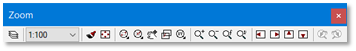
Zoom Icon Bar
When importing or exporting graphical images to and from AutoCAD, you will be asked to nominate a viewing scale. This is because AutoCAD treats text sizes in ground units. For example, if you wish to plot 2mm high text in AutoCAD with a viewing scale of 500, a simple back of cigarette pack calculation is required.
Text size (m) = 2mm * 500 / 1000 = 1m
Changing the viewing scale in n4ce will resize the text appearing on the screen and NOT the overall view.
Using Text in the Code Table
There are several different tools within n4ce to handle the display and plotting of text. Core to the placement of any survey detail, including text, is the Code Table.
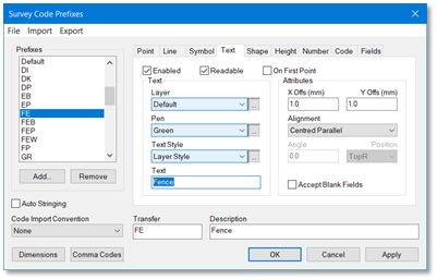
n4ce Code Table - Text
n4ce will translate all the enabled elements within the Code Table into detail at the coded point. For example, if the code for a fence is FE and the Text tab is enabled, as above, then text Fence will appear on the layer Default. With a text Style and Pen which is taken from the layer defaults, located 1mm offset from the point and midway between nodes on a line, as shown below.

Further text plotting options are available, as can be seen in the view below.
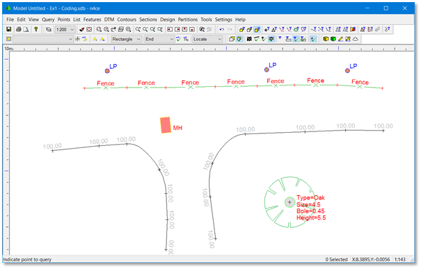
Different Annotations Displays from the Code Table
The LP text on the lamp posts and the MH text on the manhole are added to their codes in a similar manner, considering the Alignment and offset Attributes. The text associated with the tree is added using a Text Macro.
A Text Macro converts Dimensions and point attributes (px, px, pz etc) into annotation that will appear on the screen. These macros come in three parts, namely
<Label1>%<Dec.Dimension>%<Label2>\n
For example, Type=%TP%\nSize=%.1S%Bole=%.2R%\nHeight=%.2HT% (see above for final display)
There are three types of Dimension.
- Coded Dimensions eg S=<scale>, R=<radius> (variable)
- User Dimensions eg TP=<type>, HT= <height> (variable)
- Point attributes eg px=, py=, pz= pc=, pn=, rem=, chn=, brg=, rad= (fixed)
Dimensions are case sensitive and be careful not to specify them twice! For example, H= for horizontal offset and H= for height of a tree otherwise your points will be offset from their true position!
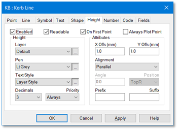
Height annotation is treated slightly differently to Text, Number and Code, as has additional attributes.
Height Coding
Layer, Style and Pen are as other annotation items, but we now have the addition of Decimals, Priority, Allways Plot Point, Prefix and Suffix. The decimals attribute applies to all points with the same code.
If there’s height text dispayed on the screen, for example a spot level, you can force the point symbol associated with these levels to be plotted even though the layer it falls on is turned off or the layer override option has all point markers turned off. This is forced using Always Plot Point.
The Prefix and Suffix option are provided to add text before and after Heights, Numbers or Codes. For example MH 123.456mAoD. MH is the prefix and mAoD is the suffix.
If text is aligned to follow a feature, there is every chance it may go through the vertical and appear upside down. The Readable option, if set, will flip the text making it easier to read. For features that possibly only need to show the height on the first point, for example a contour, the option On First Point can be used.
Text editing options can be found at the bottom of the Points menu, in model graphics. All detail you see graphically, including text, is drawn ‘on the fly’ using the Code Table. If you make changes in the Code Table, the next time you redraw the new setting will be seen.
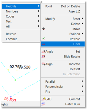
Height Annotation Edit Menu
Features and text are not stored in the model, only the point and its attibutes, so when editing text the prompt asks you to indicate the point and n4ce will identify the text item attached to that point, from its offset and orientation.
Editing Text – Identifying the Point
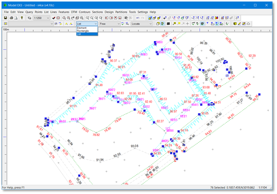
A very useful tool is available to identify overlapping height text, called Filter. This works with the List pick option and allows you to identify overlapping height text based on a Priority. This must be set in the Code Table prior to running this option and runs from 1 (low) to 9 (high).
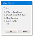
Height Filtering
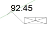
The Height Filtering dialog box will appear identifying options. Overlapping height text will be identified and placed on a List. Listed points appear with a yellow or blue rectangle blob over the point depending on your background display option.
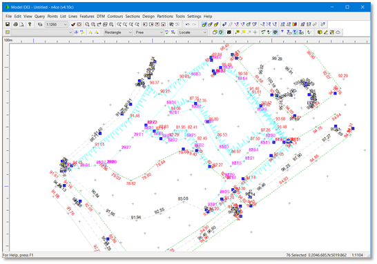
Listed Overlapping Height Text Points
Points with lower priority overlapping height text will be identified and placed on the List, which is shown here bottom right as 76 Selected. You may then use the List Pick Mode and Heights Delete to remove the lower priority height text, leaving the blue (yellow) height light in place, where text has been removed. This allows you to use the Restore option to bring the height back on selected points. But don’t forget to set the Pick Mode back to Element, otherwise all the listed point height text will re-appear!.
Filtered Overlapping Height Text
Further edit option can be found in the Points menu, including handling parallel and perpendicular text.
Text Display Options
Text can be turned on or off in a number of different ways. Firstly by layering and secondly by Object, or Layer Override. Point annotation will only appear if the Code Table item has been activated first.
The Layer icon (three slices of bread) can be used to turn layers on or off. A special object layering button called Override (ALT+F9) can be used to turn different objects on or off irrospective of which layer they fall on.
| Note: the Snapshots button in Layers dialog allows you to record and save the current layer status and return to this layer staus later on. Also note the CAD option in the Layer Override dialog. This is controls the Dedicated CAD Backcloth display, discussed later. |
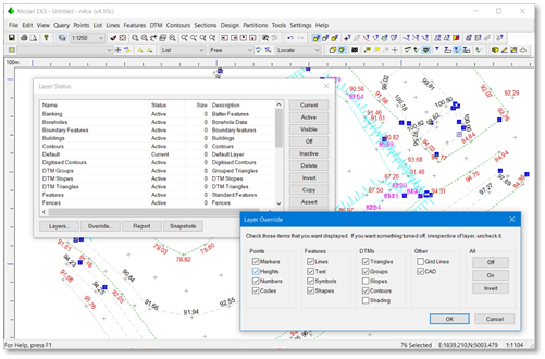
Model Layering including Layer Override
When working in graphics there an icon bar is available which controls the display of All annotation. This is in the Display icon bar and the individual Text display icons have a T. The T with a blank turns on/off all annotation whilst the T with a box replaces the annotation with a box. This can be used to speed up redraws and intially tidy up the display. The T with a tick displays text normally whilst the T with both tick and a box show you where text should appear when plotting or exportig to AutoCAD DWG/DXF.
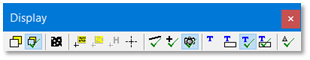
Display Icon Bar
|
Note: Some text is unstable when zooming in or out, stretching beyond the extents of the reference box. Most normal Windows fonts, like Arial and Times Roman are well behaved and its only the obsure fonts that we have difficulty with. But the box does indicate the true position in both printing and export to AutoCAD DWG/DXF. |
Text Styles are defined in terms of a Windows Font, a Frame, Size, Stretch, Italic and Bolding. When exporting to DWG/DXF the View Scale must be presented. AutoCAD views text in ground units whilst n4ce views text in mm at the final plotted drawing scale. The framing, except underline, will appear in AutoCAD as a separate element.

Defining Text Styles
Adding CAD Text to a Backcloth
n4ce has its own CAD editor which can be accessed from the Project Tree. When used in conjunction as a backcloth this allows the addition of further detail to your surveys, models or another CAD folder. Remember the detail you see in a model or survey is generated from the Code Table. Anything drawn in CAD is “static” and unaffected by the Code Table. Each model has its own Dedicated CAD Backcloth that can be accessed using the Pencil Icons from the Edit icon bar.

Edit Icon Bar
Normal CAD tools are available here. If you have the model and dedicated CAD views open at the same time, zooming into one view will automatically zoom into the other view. If you apply a coordinate transformation in a model with layers in the dedicated CAD backcloth turned off, then the transformation will only apply to the model and layers turned on in the dedicated CAD backcloth.
The Pro&Des editions have the access to additional plotting tools in a model, including Hatching and slope symbols which we call Hatchuring. These can be found in the Tools menu.
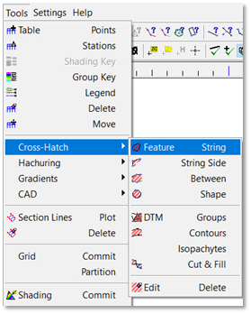
CAD Tools in a Model (Pro&Des)
The dedicated CAD backcloth shares the same layers as the model it belongs to, so CAD detail can appear on the same layer as say features. The dedicated CAD backcloth can be turned On or Off using the Layer Override option which can be accessed from the layer’s icon or using the ATLT+F9 hot key.
Since the option to add CAD and/or model folders as a backcloth to an existing model we must provide a mechanism for identifying which CAD or models are active in a backcloth. This is done by selecting one of the three yellow backcloth icons in the Query icon bar.
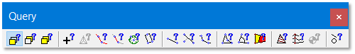
Query Icon Bar
The first icon interrogates the model and its dedicated CAD backcloth. The second only looks in normal backcloths, whilst the third looks in either/or. We’d recommend leaving it with either/or unless you need to be specific!
Final Presentation Drawings
n4ce has tools to generate final presentation drawings, using both Paper Space and Model Space. Drawing Templates are used to prepare blank sheets with Title Boxes, Legends and other standard detail. Viewports can be added which are made up of data folders found on the tree, possibly combining these to generate an overall view in model space. CAD tools are provided to draw detail, including text, in paper space.
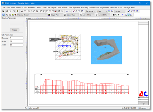
Final Presentation Drawings – Paper Space & Model Space
Comments
0 comments
Please sign in to leave a comment.