Before trying to process your first survey, sort out your Defaults including Code & Layer Tables and Symbol Library.
Defaults are stored as INI files in a ..\Settings folder, accessed through the n4ce Support Files Icon on your desktop.

When you start a new Project, these global defaults are copied into the current Project. Any changes you make to these settings only relate to the current Project. If you press the Save button, you will be invited to confirm overwriting the global defaults, in the ..\Settings folder.
Note: Each Project, or SDB file, contains its own defaults, codes, layering and symbols, which are unique to that Project. Recalling a previously stored Project will recover these defaults and symbols.
Models used in Projects have their own layers, initially copied from the Project layers. This allows each model to be shown with its own layers turned ON/OFF without effecting other models, or CAD folders.
Note: Create new layers at the Project stage. You will be asked to Assert them into existing Models in that Project.
Current Project settings (defaults) can be overwritten using a Reload option, and in the case of Layers and Codes, from backups stored in sub-folders on your hard disk.

New From – Copying Defaults
You can create your own “empty” Projects containing their own defaults. These empty Projects are called Client Templates. They can be opened like any other Project and used to form new Projects by using Save As.
Note: You can also use the New From option in the File menu to copy the settings from an existing Project into a blank Project, then save this with a new name.
Feature Coding
Core to how n4ce works is the Code Table. This converts your survey feature codes into graphical elements and unlike CAD is dynamic. Making changes to the codes will cause a ripple through effect in related graphic views.
Before we look at the Code Table, let us investigate how n4ce handles feature coding.
Feature codes are made up of three components, namely a Code Prefix, and optional String Number and/or optional Comma Codes. For example: A delimiter character separates the comma code from the prefix & number.
<Code Prefix> <String Number>, <Comma Code>
KB01,CX – could be Kerb 01, with curve fitting and not included in the DTM
BB,N – could be the first point on a new Bottom of Bank
TR – could be a tree. This would also have Dimensions (see later)
Data can be viewed in both spreadsheet format (control grid) and graphically. Each access the same part of the database, so that changes in one view will be reflected in the other. This is called duality of display & edit and works well with twin screens.
Multiple graphics views can be displayed, with changes in one view being updated in others, simultaneously.
The line work in the example shown below, is controlled using the comma codes N for new feature, C for curve fitting and P for closed polygon.
Points relate to lines if they have the same code and are sequential in the control grid.
Editing is possible in the control grid using right click menu options, which are column sensitive. An Order option is provided to help here, to link points with the same code. Also see Auto Stringing in the Code Table, overleaf.
|
|
|
| Multi-Views with Feature Plotting |
Trees, lamppost and manhole have additional attributes, called Dimensions, which provide sizing and textual detail.
The Code Table
Survey feature codes can generate graphical objects for Points, Lines, Symbols, Text, Shapes, Height, Number and Code annotation automatically, controlled by the code table. Each object has its own tabbed page with settings including Layer, Pen, Size and Style.
Where sizes are given in mm, these are related to the paper or Viewing Scale. Please make sure that scales are set correctly before exporting to AutoCAD.
Upper and lower-case characters can be used in layer names, but avoid using non alphanumeric characters such as #@\% etc. as AutoCAD may object to these.
The Transfer option is used for MX GENIO formats.
Auto Stringing, if checked, will link points with the same code, even if measured from a different station.

n4ce Code Table
The code table uses a file called Codes.ini and works in conjunction with Layers.ini, both stored in the ..\Settings folder, found in the short cut Support icon on the desktop. Additional codes/layers can be created and stored in sub folders and saved/accessed using the File menu.
File menu is used to Load, Save, Merge and Purge codes. The merge option allows you to combine different codes, recalling the addition from a sub-folder. But remember to also update your Layers as well.
The Purge option is used to reduce the code table to just the codes you are using. You will be invited to select the codes you still wish to retain.

Purging Codes
Two further menu options are provided, called Import and Export. These allow you to communicate with GPS/Total station instruments, reading in codes or exporting n4ce codes for use in the field. In the case if the export, the options include XML which is becoming the preferred data transfer format for handling survey data. One of the advantages of using the n4ce code table on your instrument, is that prompts will appear for attributes. We’d also recommend Quick Codes on Leica instruments, when using Captivate software. The only issue with Importing and Exporting n4ce codes will be the layering, which may require some manual editing.
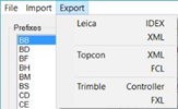
Exporting Code Table
The Comma Code button at the bottom left of the screen, displays the most commonly used comma codes, controlling lines and points. The Ignore code is used with survey observations, to eliminate these readings from consideration during reduction or adjustment. You may change the character definitions to your own preference. For example “C” to “K”
The standard Separators are set to a comma “,”, minus “-“ or dot “.” but can be changed to a more suitable character if required.
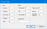
Comma Codes
Whilst Dimension may appear similar to Comma Codes, they have a different purpose and can control the size of detail being plotted, like line widths and the size of manholes.
There are three types of dimension, namely Codes, User and System. When used in conjunction with Text Macros, can be used to display additional attributes on the screen.
For other instrument coding, use Code Import Convention.
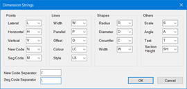
Code Dimensions
Four options are available: (“_” are spaces)
- None ignores any additional entries and treats them as part of the code. This is the standard setting.
- AiC (Dim Labels) – Code_Comma Codes_Dim1_Value1_Dim2_Value2 etc.
eg. TR_Z_S_4.56_R_0.25 – gives the tree code dimensions S=4.56 and R=0.25 and comma code Z - AiC (No Dim Labels) – Code_Comma Codes_Value1_Value2 etc.
eg. TR_4.56_0.25 - gives the tree code dimensions I1=4.56 and I2=0.25
Geosite is like the AiC (Dim Labels) option, but has other features which recognise Geosite coding.
Layers, Pens and Text
Each of the object types identified in the Code Table, will be allocated to a user definable layer. Since both upper and lower case character can be used, layers can have the same name with different case characters. When exporting to AutoCAD v14 or earlier, all characters are set to uppercase and spaces are replaced with an underscore.
 Layers can be accessed from the Settings menu, or via the button with three dots to the right of the layer combo box, in the Code Table. The latter is used as a short cut to the layers dialog.
Note: when a Model is created layers are copied from the Project and become unique to this Model. If you add a layer to a Model this becomes unique to that Model and will not appear in Project layers used in the Code Table. If you create a new layer in the Project, models already created will not see this new layer unless you use the Assert option in Model layers to copy this across. Warnings will be given!

Model Layer Status
n4ce Layers has an option called Override, allowing you to turn objects on/off, irrespective of the layer they fall on. This is where you would turn on/off the Dedicated CAD Backcloth, Shading and Grid Lines.

Layer Override
Each layer has its own defaults for Pen, Style, Size etc. and when selecting a new setting, the option to use the By Layer Style can be selected. A Default layer is available, wherever a layer is missing.

Layer Defaults
Text styles use Windows Fonts and a Size, in mm, at a reference scale Stretch and Boldness. Text styles can also be Framed.

Text Styles
If you press the button with three dots to the right of the combo box this take you to the defaults related to that window, as a short cut like Pens. n4ce supports 256 Pens (Colours).

Pen Defaults
The commonly used pens are identified by name, all others by a number. The names of pens can be changed along with line weights. Options are also available for controlling the display of line weights and plotting in Black and White, as shown above.
![]()
Zoom Icon Bar Showing the Scale
When exporting to AutoCAD DWG/DXF, it’s important to set the correct object scale. The Size of points, text and offsets are in mm at the final plot scale. Text on a 1:500 drawing will appear larger than on a 1:250 drawing when viewed graphically. This scale also affects the repeat pattern on line styles.
Before we leave the discussion on layers, you will see there is a button called Snapshots. This allows you to record the current layer status of a view and recall it later, after layers have been altered.
You have options here to Select, Create, Update and Delete.
These Snapshots will be remembered when saving projects and apply to both CAD and Model folders.


Snapshots
Points Tab
There are 21 different fixed point styles to choose from, including None and Layer Style. Sizes are in mm at the current object scale, although there is a display option that keeps them at a fixed viewing size.
Points are excluded from a DTM or a Query, if layers containing points are turned off. Model Points in the Code Table is used to include points during DTM creation.

Points Tab
Note: During DTM creation, duplicate points will be identified, with only the first point found being used. It’s not possible to create vertical faces in a DTM, so if you want near vertical faces offset points by at least 1mm.
Lines TabA None Style has been included to allow you to query points even though there are no points visibly attached to a feature.
n4ce user defined line styles can be edited using a text editor.
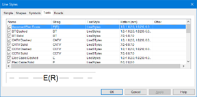
Line Styles
Line styles are stored as LStyle.ini in the ..\Settings folder and made up as a combination of Shapes, Symbols and Text.
Complex line styles, like hedges, can’t be exported directly into AutoCAD, so the shape files Markers.shp and Markers.shx are provided for this purpose.
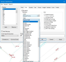
Lines Tab
Line features can be used to force Breaklines in a DTM, but if two line segments cross only the first will be used to force creases in a DTM. Line widths are controlled, where applicable, via the W= dimension. See later discussions on Fields Tab. Parallels are available with P=. Variable widths are available with POW setting.
When exporting curve fitted lines into AutoCAD, after using comma C on line features, these will be converted into either bulged polylines or short straight-line segments as defined in the Options settings. This is where you set the display for decimal places in tables and reports.
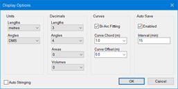
Display Options
Symbols Tab
A master Library of symbols is stored in the ..\Symbols folder, as individual files with a SYM filename extension. Each project has its own Project symbols that can be copied from the master library, when opening a new project using the Always Loaded check button.
Symbols can be created using the n4ce CAD tools directly, or imported using an AutoCAD DWG/DXF import. These are stored in the project but can be Saved to the master Library. Library symbols can be Loaded into a project.
When importing DWG/DXF files, Blocks become Project symbols. When exporting DWG/DXF files Project symbols become Blocks. Since all Project symbols will be exported you may wish to remove unused symbols using Purge.
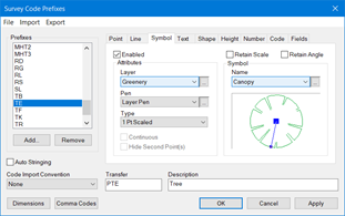
Symbols Tab
Note: Elements forming AutoCAD Blocks can appear on different CAD layers. Blocks are converted into n4ce symbols during import. Blocks are flattened so elements in a symbol will appear on the same layer in n4ce
Three different handled symbols can be created within n4ce:
1 Pt Symbols with an origin
2 Pt Symbols with an origin and a handle for scale and orien.
3 Pt Symbol uses a third handle to scale in a perpend axis.
If you import a AutoCAD files, Blocks automatically become 1 Pt Project symbols. To make these into 2 Pt or 3 Pt you have to plot them in n4ce CAD, un-nest and re-create them with a new name.
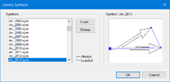
Library Symbols Viewer (Always Loaded)
Note: 2 Pt and 3Pt symbols are converted into 1 Pt Blocks when exporting to AutoCAD DWG/DXF.
Text Tab1 Pt Scaled symbols use the S Dimension to size a symbol, initially drawn at unit size. When scaling a tree, a sale of S=5.5 in the Dimension field would provide a canopy 5.5m wide. If the Dimension is missing, a default value can be allocated. The last value used can also be retained as the default.- 1 Pt Aligned will take the alignment of the string, typically for kerb gullies.
- 1 Pt Request is a 1 Pt Aligned, except the Comma Code S is used to nominate placement.
- 1 Pt Fixed would draw the same at the real size, in metres, on the finished drawing independent of scale.
- 1 Pt Ends draws a symbol at the ends of a line feature, taking the bearing of the line for its orientation.
- 2 Pt Aligned would rotate the two point symbol based on an origin and a handle.
- 2 Pt Stretched would stretch a two point symbol in the X direction. Useful for gate symbols.
- 2 Pt Scale uses the origin and handle to both orientate and scale the symbol. Useful for tree canopies.
- 2 Pt Width and 3 Pt Symbol are used to place two point symbols with a perpendicular stretch.
- 3 Pt Symbol uses the origin for its position, the first handle for a stretch in that direction from the origin and the second handle for a stretch perpendicular the first direction.
- Section Symbol can be attached to line features and will appear in section plots, when crossing features.
Text can be added to a survey using the Text tab, and entering the text in the Text window. For example, LP for lamp post.
You may also use the T= Dimension to enter variable text. The T= Dimension is very powerful and will overwrite any text previously presented in the Text window, shown below.
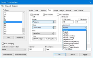
Text Tab
Text is plotted on its own Layer with a Pen and Text Style, at a position as defined by the X and Y Offset, in mm at the current plot scale. Text Alignment can be Normal, Angled, Parallel, Perpendicular or Centred.
Aligned text can be automatically flipped to make it Readable and plotted On First Point of a line feature, if these buttons are checked.
A Text Macro is used to plot Dimension and Remarks alongside the point. It comes in three parts.
<Description or Title> <% Decimals.Dimension%> <\n> - where \n is a new line
For example: %TY%\nSize=%.2S%\nBole=%.1R%\nHeight=%H% - would plot the tree. The .2 in front of the S Dimension controls the number of decimals places.
There are three types of Dimension:
- User eg TY=<Tree Type> (note: please use 2 characters here to distinguish between Coded)
- Coded eg S= <Scale>, and
- System eg REM=<Remark>, PX= PY= PZ= PC= & PN= <Pt XYZ coords, Pt Number and Pt Code>
A further example: E=%.3PX%\nN=%\.3PY%\nH=%.3PZ%\n%REM% - would plot point coordinates and a remark.
Finally, simple calculations can also be performed with Dimensions, for example %.2(PZ-H)%. The calculation is performed inside single (<expression>) brackets and can include +/-* operators.
Shape Tab
Shapes are used to describe man holes, storage tanks and bole radii in terms of a Rectangle, Circle, Arc or Triangle. They can be created using a combination of 1, 2 or 3 points with/without a size Dimension.
In the case of a circle, its size can be deduced from a radius, diameter or circumference using Dimensions R for radius, D diameter and C for circumference.
Rectangles are similarly defined with 2 or 3 points. In the case of 2 points, a width Dimension W will be required. Offsets to the left are –ve and to the right are +ve.
A Dimension W is used for the height of a 2 point Triangle.
Shapes can be filled with an infill pattern.
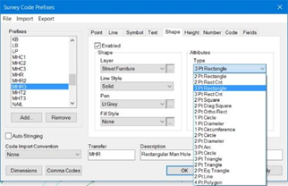
Shape Tab
There are further options to Retain Dimension, Hide Second Points, Open Rectangle and Alternate Points.
Height Tab (also Number and Code)
Height text options are like Text as described above, with additional options of Decimals, Priority and Plot Point.
Prefix and Suffix add text to Hts. eg CL=123.345mAOD.
Always Plot Point option will force a Point Marker to be plotted alongside visible height text, even if points are turned off using layers [ALT][F8] or layer override [ALT][F9].
Priority is used when Filtering height text. Heights can be weighted (highest 9) and when filtered overlapping height text items with the lowest priority can be removed.
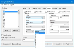
Height Tab
Note: Text editing is found in graphics Points->Height. You MUST indicate the point when editing associating text.
The Number and Code text options are very similar, with exception of Priority. No text filtering is possible here for Numbers and Codes.
The main tools used to edit your surveys can be found in the Points and Features menus. These are more fully described in other articles. But it is worth mentioning here that text editing, found at the bottom of the Points menu, work on points and not the text that is seen. Text items are not stored in the SDB and are generated on the fly.
When moving text a leader line will identify the text item being edited.

The only exception to editing text is where it’s been added in CAD. Pro & Designer users have access to the Dedicated CAD Backcloth, where they can supplement surveys with additional CAD detail.
A special Filter option is available to Pro & Designer users, that identifies overlapping Height text. Overlapping height text points will be added onto a List. Height text attached to the listed points can then be removed.
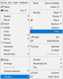
Points->Height Text Editing
The Flip, Parallel and Perpendicular options are useful, and can work on individual or all text items, associated with a line feature. You indicate the feature string here, as opposed to the individual point, unless it’s the individual point you wish to flip etc.
Fields Tab
The Fields tab is used to define the Dimensions used to size or describe objects. In the Example shown below, the Tree Canopy is defined by a Scale S and the Bole by radius R. Default values are available if you fail to provide a value. HT is used for height and TYP for species or type.
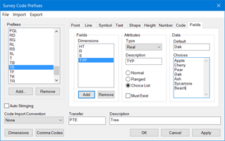
Fields Tab
Note: When exporting the code table to Leica and Trimble instruments, the Description will be your prompt on the instrument. Restrict this to 8 characters.
The Dimension identifiers, shown below, are provided as standard and describe Points, Lines, Shapes and other object types. You may change these identifiers, replacing them with I1, I2 etc. representing attributes stored on some instruments. See Technical Notes from Leica, Trimble, Topcon and Sokkia.
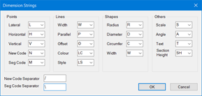
Dimension Identifiers
As you can see, there are quite a few different Dimension options. But this is not the end of the story. You may also define your own Dimension identifiers, like the example with the tree. In the Tree example, TYP and HT are not in the above coded list, but are still recognised in a Text Macro. These are user defined Dimensions.
Note: DO NOT use H= for a height as this will offset the point along the line of observations, during reductions! As a general run use 2 characters for a user dimension eg HT=.
n4ce will also create its own Dimensions, sometimes called hard coded or system dimensions. These include PX, PY, PZ, PC, PN, PZD, PP, PS, PD, REM, CHN, RAD and BRG.
An example of their use would be the attachment of chainages to a linear feature, or displaying X, Y & Z coordinate text alongside a Station.
The Features menu of the Pro & Designer editions, has options for Chainages, Radii and Bearings. These will add Dimensions to feature strings you indicate and can be plotted using a Text Macro as shown below.
Ch=%.3CHN%m
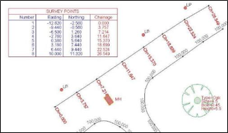
Adding Chainages to a String and Plotting the Table
A Points Table containing Dimensions can also be plotted in the Pro& Designer editions, shown above. Items can be defined in a table profile and stored for later use.
Querying Points
![]() Query Point also acts as a mini Point Editor, allowing you to change the Code, Number, Coordinates or Attributes as required.
Query Point also acts as a mini Point Editor, allowing you to change the Code, Number, Coordinates or Attributes as required.
In the example shown below, a Tree has been queried. Remarks and Dimensions can be modified, with a ripple updating both graphics and spreadsheet views.
The Code button jumps straight to the code page for this feature. A Report button provides exports to a printer or file.
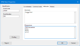
Query Point Attributes

Querying Features
![]() Query Line has some nice features, like showing you the profile of the line and allows you to reverse its direction. The first point is identified with a large blob.
Query Line has some nice features, like showing you the profile of the line and allows you to reverse its direction. The first point is identified with a large blob.
If you move the focus to another point in the list, a vertical bar will move to that point in the profile. Also, a different coloured blob will be seen in plan at this position.
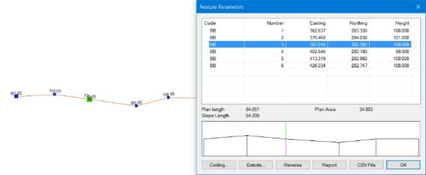
Query Line Attributes
Note: if you double click on a line in the list, you will enter the point editor as shown above, for that point.
Feature Reporting
An option has been added to the Tools Menu in the Survey View, Report Codes, and the Features Menu in the Model View, Report. This allows you to generate a report of the feature codes used in a survey or model. Selecting the option will cause a dialog box like that shown below, to be displayed.
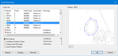
New Feature Reporting Option
The Code List displays a list of all the features that are in the survey or model. The content of the list control is governed by the group of radio buttons underneath, with four options:
- All Features will display all the features in a survey or model.
- Undefined Feature Codes will only display features where the feature code is not recognised from the list of defined code prefixes
- Features with Warnings will display undefined feature codes together with features where the number of points is incompatible with the generation of multi-point shapes and symbols or a dimension is missing from a point
- Used Feature Prefixes will display all the feature prefixes that have been recognised
When displaying a feature, a green tick signifies that its code has been recognised and that there are no problems with the point count. A red cross indicates otherwise. Other information is displayed, such as the number of points in the feature and some details about the prefix that has been recognised.
Highlighting a feature in the list control causes the graphic view to the right to be updated showing where the feature is. Double-clicking on the list control will bring up the Query Feature Dialog Box for the highlighted feature.
When displaying the prefixes used, the number of features that use that prefix together with some details of the prefix are displayed in the list control. In this case, the graphic view contains an indication of the position of all the features using the highlighted prefix.
The Report button generates a text report depending on the list control. The Coding button allows you to change the settings for the prefix used in the highlighted feature or prefix. The Recode button allows you to recode a feature and is only available in the Model View. + and – buttons allow you to zoom in and out of the graphics window on the right. Panning is not possible.
Any changes you make to the feature codes listed will only be saved in the project when you select the OK button and leave the dialog. If you have made changes to the code prefix table, however, these changes will always be retained.
Plotting, Text and AutoCAD DXF/DWG Output
It’s possible to create plots at any time using the Print Preview Icon, or the print option from the File menu. n4ce works based on what you see is what you get (WYSIWG), at whatever screen scale you are working with, but not necessarily to scale. Screen grabs can be taken by using the [ALT]+[PrtScn] hot key combination.
You can control the screen scale using [ALT]+[S] for zoom scale, but again this does not necessarily the print scale.
Drawings should be used to create final plots with title boxes, legends at fixed paper sizes. Both paper space and model space are used here, with multiple view ports.
Text used in n4ce is nominated at a fixed size in mm which is different to how AutoCAD deals with text, using ground units, i.e. metres.
It’s important to specify an n4ce viewing or object scale when creating new graphics data folders (Observations, Co-ordinates, CAD and Models). Text will then appear in graphics displays to the correct size, in mm units, to this scale when plotted or exported to AutoCAD.
For example, text with an object scale of 500 will appear larger on the screen, than an object scale of 200. The screen text size is bigger, but the plot text height is the same! The same object scale must be used when exporting to AutoCAD.
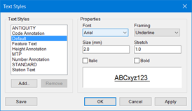
Text Styles - Definition
At some stage you will need to create an export file using the File menu as shown below. This is a view from a model in graphics, but a similar option is available in Observations, Co-ordinates and Drawings.
There are two options here, Standard and Realimation (Models). The latter option is reserved for creating a 3D export to go into a virtual reality package.
Having selected the Standard option, you will be invited to provide a filename and location where to store the saved file. You will be invited to choose the file type, including DXF or DWG.
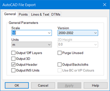
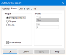
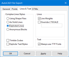
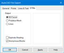
Four tabbed pages provide defaults for AutoCAD File Export.
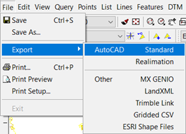
Exporting DXF Files
General tab controls the scale, units and AutoCAD version. The Output Header option exports symbols used in the project. Where you are adding to an existing AutoCAD drawing, this may not be necessary. n4ce has a concept of 2D points. These are converted to a valid level, using “D Height. If you use a SHP file to plot complex line styles these will be shown as solid lines in AutoCAD. These will only show as complex lines when exported as 2D.
The Points tab controls point types. AutoCAD can only show one construction point size and type, so most people use the Symbols option as types and size can vary. If you wish to embed the height, code, number and other attributes within the point symbol, enable Use Attributes.
The Lines and Text tab controls how complex lines will appear in AutoCAD. n4ce has its own user line styles, like hedges, escarpment etc which are not available in AutoCAD.
|
General DXF Defaults |
Point Defaults |
|
Line Defaults |
DTM Defaults |
General tab controls the scale, units and AutoCAD version. The Output Header option exports symbols used in the project. Where you are adding to an existing AutoCAD drawing, this may not be necessary. n4ce has a concept of 2D points. These are converted to a valid level, using “D Height. If you use a SHP file to plot complex line styles, these will be shown as solid lines in AutoCAD. These will only show as complex lines when exported as 2D.
The Points tab controls point types. AutoCAD can only show one construction point size and type, so most people use the Symbols option, as types and size can vary. If you wish to embed the height, code, number and other attributes within the point symbol, enable Use Attributes.
The Lines and Text tab controls how complex lines will appear in AutoCAD. n4ce has its own user line styles, like hedges, escarpment etc. which are not available in AutoCAD.
Three options are available here for exporting lines:
- a) Convert all complex line styles to solid,
- b) Explode all complex lines into 3D polylines, or
- c) Use Shape files. In this latter option you will have to use two files called Markers.shp and Markers.shx which can be found in your ..\Settings folder (see n4ce Support Files icon on your desktop). Copy these two files into the root folder containing AutoCAD. You must supply these two files with your DXF/DWG file when passing these onto another user. AutoCAD can handle lines with text embedded so you do not have to explode these.
The DTM tab controls how DTMs are exported within the DXF/DWG file, if present.


Comments
0 comments
Please sign in to leave a comment.