
There are two ways to display your survey as graphical elements, namely CAD and Model. In the latter a lookup table converts survey feature codes into graphical elements. A Code Table is used in n4ce to create Models.
n4ce feature coding is made up of a Code Prefix, String Number, Comma Code and Dimensions.
<Code Prefix><String Number>,<Comma Code>
For example KB12,C1X is a curve (,C) fitted kerb (string 12) using dot point style (,1) and ignored in the DTM (,X).
Whilst it not absolutely essential to use a feature code or point number when surveying, or importing data into n4ce. If feature codes are not found in the Code Table a Default code will be allocated to these points.
Note: When identifying codes, n4ce compares the whole string up to the comma code, if present, taking characters off one at a time from the right until a match is found. eg KB12. If this is not in the code table n4ce looks for KB1, then KB etc. Characters taken off become the string number. Any alpha/numeric characters can be used for the code and/or string number. For example 123ABC is a valid code for 123 and string number ABC.
Lines are generated from point codes, to create polylines. These lines are virtual, so deleting or moving a point will influence other elements attached to this point.
Lines have their own definitions in the Code Table including Layer, Style & Pen (Colour).
These are supplemented by Attributes
- Width Scalable
- Variable POW
- POW on First Only
- Close Ends on P & W
- Force in DTM
- Auto Close
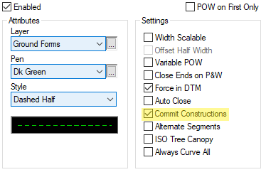
- Commit Constructions
- Alternate Segments
- ISO Tree Canopy

n4ce Code Table - Lines

Curve Fitting Using Comma Codes

Comma Codes
Comma Codes control addition of line features attributes like curve fitting, gapping and closing features. An example of curve fitting is shown below.
Curves need a minimum of 3 points with ,C code. (eg KB,C) Tangent points can be created off straights using ,T with only 2 points, but a 3rd ,C centre point is recommended.
The display of curved features is controlled from by the Settings->Options menu. There are two options here, Bi-Arc Fitting and Curve Chord. The former generates curve fitting using compound arcs, the latter uses short straight lines, called chords.
When exporting to AutoCAD DXF/DWG, the Bi-Arc will generate bulged polylines which may not be an option in another CAD system. The chord length, if used, must be sufficiently short to show the smallest radius arcs, like islands in roads

Setting Curve Plotting Tolerances
Curve features are stored as an equation in n4ce, so the options shown here are for display, export and plotting. The chord length, if used, must be appropriate for the smallest radius curves. It means other curve fitted features must use the same chord length, resulting in large AutoCAD DXF/DWG files.
Dimensions are also used when plotting line features, including line widths, parallel and offset lines, colour and style of a line feature, as shown below.

Code Dimensions
Two additional options appear here, which can be very useful. These are New Code and Seg Code, which allow you to create 2nd codes at a point. Seg Code is used to change a segment between two points, e.g. adding a drop kerb or gate. (See later for discussion on Separators).
Section Height is used with underground services and where crossing line features on section plots.
String or line features are very important to n4ce, being used in many ways, such as providing a reference to align other items like text and symbols, as shown below.
If Symbol Attributes are set to 1 Pt Aligned or 1 Pt Request, it’s important that symbols are created with the origin on the top or bottom of the symbol, depending upon the direction of the feature. Comma Code S is used to add symbols at requested points.
Text items can take their orientation from a line feature. Again, the side the text falls on depends upon the direction of the line. Edit options are available to flip text from one side of the line to the other.

Symbol Aligned Option
The chainages labels shown below are created using a Text Macro.

Text and Symbol Alignment Controlled by String Features
Force in DTM is used during DTM creation to force Break Lines. Features used as break lines should not cross, but if they do, the DTM formation process will retain the first crossing break lines and ignore the second. A CAD layer called DTM Errors highlights inconsistencies.
Edit tools are provided for modifying DTM triangles including Switch, Line, Feature Forcing and Apex options.
|
DTM – No Break Lines |
DTM – With Break Lines |
The Auto Close Attribute used in a feature line definition, is equivalent to adding a Comma Code P to close a line feature onto its starting point. The closing leg will be used in forcing break lines.
Note: There are restrictions on editing closed features. You will be prompted to open the closing leg before editing.
Parallel and Offset Lines – Using Dimensions
There are situations where twin or duplicate lines are required; typically when measuring walls, or a track. Here, the surveyed point will generate the line feature but not necessarily passing through the surveyed point. The point and not the line will be used in the DTM, including forcing if applied. Read on further for adding both lines into a DTM.
Useful Dimensions here are Width (W=) Parallel (P=) and Offset (O=), which can appear on the first or last point on a feature, unless P,O&W on First Only is checked. W, P & O can be replaced by I1, I2 etc. for certain loggers.
Feature lines are controlled by the Lines tab in the Code Table. If you are using Line Dimensions you should set a default value in the Fields tab, as shown below, so that missing values will be taken from these Attributes.
If you are measuring a hedge with W=, you can offset the hedge by half its width.
|
Line Code Definition |
Fields - Default Line Attribute |
Note: Closing Ends on P&W will form a closed polygon on these lines P= and W=. Those shown below are open.
For none scalable lines, three Dimension are available.
W= produces two equally spaced parallel lines either side of a centre line.
P= produces two lines, one passing through the points the other at an offset.
O= produces a single line offset from the original point.
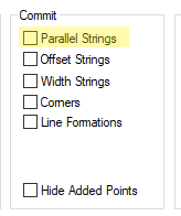
VP= Creates a specific amount of strings with certain vertical intervals. Note: You will need to have commit constructions enabled under the Lines Tab in the Code Table. In addition to this have the check box parallels ticked when creating the model.
In all cases –ve values appearing left and +ve to the right of the line, in the direction of the feature.

Dimension W= <Not Width Scaleable>

Dimension P= 10.0

Dimension O= 10.0
For width scalable lines like hedges, the Dimension W= is also used. Lines can be offset half their width by setting the Offset Half Width option. (–ve width is left).
You may also alter the repeat pattern on none scalable lines by using W=, with width scalable set.
The repeat pattern always starts and finishes at the end of each line. The pattern is stretched to fit.

Dimension W= <Width Scaleable>

Dimension W= Width Scaleable and Half Offset

Dimension W= <Width Scaleable>, Repeat patterns
Variable Line Widths
The W= Dimension can also be sued to create variable line widths, like hedges.

If you wish to have variable width lines, like a hedge, a different approach needs to be taken. It’s unlikely that you will want to identify the centre of the hedge, measuring just one side and applying an offset or parallel line representing the other side, the same as offset half width mentioned above. Here you would use the P= Dimension.

Special Internal Use Dimensions are used here, defined in the Fields tab of the feature code being used, to create the line feature on one side. The Dimensions FCL= defines the centreline code, if used, and FPL= defines the parallel offset code. In the example shown below, the feature passing through the surveyed points is HER, with a line style for half a hedge to the left, and FPL=HEL which has a line style for half a hedge to the right. A separate line representing the centreline has been added with FCL=CL.
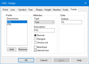
Setting the Internal Use Dimensions
Changing Line Attributes – Using Dimensions
Two Dimensions are used to alter the Line Pen and Line Style for a line feature, keeping the same code. These Dimensions must appear on the first point on a line feature.
LC= is used to change the Pen (colour) of the line segment, numbered between 0..255 (256 colours).
LS= is used to change the line style in the segment and uses the name of that style.
Where a line feature changes at a common point, n4ce allows the definition of the second feature using a Dimension. For example, where a fence or hedge meets a gate and then continues with the original feature. This is done using either the M= or N= Dimension, the result being similar.

Inserting a Gate Using N=GT

Adding a Gate using the N= Dimension
But, as you can see, the N= solution appears to break the feature into two, so if you order codes or reverse the feature then detail will be lost.
In the M= solution, the width of the feature remains the same and only the segment is changed. Reversing or ordering codes does not destroy the detail.

Insert a Gate Using M=GT

Adding a Gate using the M= Dimension
Code Separators – Replacing Dimensions M= and N=
Two code separators have been introduced, that allow you to replace the Dimensions M= (segment) and N= (new). Instead of using the Dimension M=GT, simply extend the feature code to HE\GT. Likewise, the dimension N= can be replaced by HE/GT. The separations \ and / are user definable, but do not use characters that would conflict with comma code separators and DO NOT use a semi colon “;” as this is a reserved character.

Hash Codes (#)
Hash # coding can be used to identify multiple line features meeting at a point, but ONLY works on imports and involves using multiple codes delimited with a # character. For example, the code BB1#TB5#FE will provide additional links to the source point BB1, to TB5 and FE. n4ce will generate additional observations or coordinates for the # codes. The import conventions for Dimensions and Comma Codes still apply. eg HE_W_1.2_#FE_#DB. Here a hedge with a width of 1.2m will be joined to a fence and a building at the same point. (“_” are spaces).
Segmented Lines
Road marking line styles were added to n4ce in v2.00. These have been recorded in the LStyles.ini files, as described below.
There are two options when generating segmented lines in n4ce. Firstly, to use a dashed road line style, and secondly to use the segmented option, shown below in the code table for lines.
The line style will be stretched between points as indicated below, creating gaps. The line remains continuous so can be curve fitted, used to force break lines, generate chainages and create parallels.
The ends of these special line styles will be closed automatically. In the example, a Solidx300 style has been used.
Gaps can be created using the G comma code. Also look at the Dimensions N= and M= to change codes.
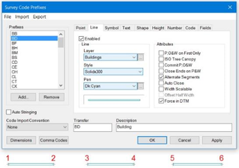
Segmented Lines
User Defined Lines Styles
The line styles used in n4ce are stored in a file called LStyles.ini and also reference Markers.ini, both stored in Settings folder, accessed from the Support Files desktop shortcut icon. These line styles are loaded into a new project from this folder and then stored within the SDB when you save the project. If you decide to update the line styles in an existing project, the Reload option will load both files.
When exporting via DXF, you may need to explode complex line styles or user shape files, called Markers.shp and Markers.shx to recreate these styles in AutoCAD. But, if you use shape files, the lines created in AutoCAD may not look the same as in n4ce, as we adjust the repeat pattern so they start and finish at the ends of a line segment.
Note: It is essential that you supply the Marker files if you are using shape files. These files should be copied into the root folder of AutoCAD on all the machines using this data – even if it has been converted into a DWG. 3D polylines will appear in AutoCAD as solid lines, even when their properties show that they are complex!
Line styles are user definable, but care should be taken if you elect to make changes, adding or modifying exiting definitions. If you do this then the Marker.shp file will no longer be correct, unless you know how to edit this file in AutoCAD. Our preferred option would be to explode complex lines. When exploding lines, these will appear as fragmented polylines in 3D, unless of course you use the 2D DXF/DWG option.
Line styles can be viewed in Settings->Line Styles and are composed of Simple, Shapes, Symbols, Texts and Roads where shapes, symbols and text will be embedded into the line styles.

n4ce Line Styles
There are 24 standard line styles that pass into AutoCAD without being exploded. These include solid, dashed, dash dotted and combinations of the same and identified in the LStyles.ini file under the [Simple] header.
Other tabs contain complex line styles as shown opposite. A preview of the line style is available.
Sample line style definitions are shown below.
[Simple]
Border=4.0,-1.0,4.0,-1.0,0.0,-1.0
Border Half=2.0,-0.5,2.0,-0.5,0.0,-0.5
Border Double=8.0,-2.0,8.0,-2.0,0.0,-2.0
The units are in mm at the current viewing scale [ALT][V]. In the Border example above 4.0 is a line 4mm long, followed by a gap -1.0mm long, then another line 4mm long etc. A dot is created where 0.0 is used.
A special line definition for [Road Markings] has been created, with distances measured in metres.
[Road Markings]
Solidx100=5,0,0.1
Solidx150=5,0,0.15
Solidx200=5,0,0.2
Solidx250=5,0,0.25
Solidx300=5,0,0.3
The first dimension, 5, is the line length, the second, 0, signifies a solid line and the last dimension is width, 0.1.
Some line styles create shapes, like hedges, or have embedded characters or symbols like [Fence] shown below. This is where the Markers.ini file links to the LStyles.ini, to provide a definition for the embedded symbol. Just for your information the Marker.ini file contains definitions for all the point styles used within n4ce.
[Fence]
Pattern=7.2,-1.6,7.2
Marker=Vertical
XOffset=8
Size=1.6
NoStretch=1
Pattern works as previously described, in mm, with –ve values defining a gap. The Marker is the symbol as found in the Markers.ini file and XOffset is the position of the symbol. The size of the symbol is as shown here, 1.6 and NoStretch=1 allows the symbol to stretch as necessary to complete the repeat pattern.
A further line style has text embedded in it, like the [GAS Route Dashed], shown below.
[GAS Route Dashed]
Pattern=1,-1,2,-1,2,-7,2,-1,2,-1,1
String=GAS,LineStyles
XOffset=10.5
Size=1
NoStretch=1
Readable=1
The Pattern is measured in mm, with negative values creating a gap. The string embedded in the line will be GAS as shown below, with a style also shown here as LineStyles. If this does not exist the Default Text Style will be used.
The text will be positioned at the XOffset, with a size as shown. NoStretch=0 (Default) will not stretch the text to complete the repeat pattern and NoStretch=1 will allow stretching. Readable=0 (Default) does not rotate text so that you can see it, whilst Readable=1 will rotate the text if it passes through 90degs.
When this line style passes over to AutoCAD, via a DXF/DWG transfer, it is automatically recognised, just like the [Simple] line style, even if you explode complex line styles. But, we can’t guarantee that what appears in AutoCAD will look the same as n4ce. AutoCAD does not support stretching of repeat patterns to start and stop on the repeats. With embedded text, this may appear at different locations and does not support our readable feature. This is best achieved by exploding the text as well.

Exporting Text Embedded Line Styles
AutoCAD line styles have their own scale which can be overridden by ticking the Override LTSCALE option, shown above.
In all cases where a symbol or text is used in line style, if the segment being plotted is too short to place the symbol or text then the segment will be plotted as a solid line.
Auto Stringing and Code Import Conventions
n4ce expects data to be sequentially recorded in the order it is to be plotted. When a code changes, this signals n4ce to stop drawing the current feature and start a new one. A special option in the control grid (spread sheet), called Order by code will organise this for you, bringing together all the features with the same code, closing gaps.
When working with survey data n4ce can also organise theses strings for you. This is done by checking Auto Stringing in the Code Table or Options from the Settings menu. When you create a Model from an Auto Stringing survey, n4ce will automatically order the codes for you, so they appear as they did in Observations or Coordinates.

Code Table – with Auto Stringing

Options – with Auto Stringing
The Auto Stringing function links points together with the same feature code and string number, in the order they are found. Joins will be made across survey station set-ups, if you continued a feature.
Note: Auto stringing only works in Observations and Co-ordinates. Alternatively, use Codes-->Order in Model Grids.
The Code Import Convention, shown above in the Code Table, has been introduced so that n4ce can handle different methods of recording feature codes with Comma Codes and Dimensions, including all in one string. This was implemented for Sokkia users, but has now been made available to other users. If you are happy with the way you are logging data, then you need to leave the option set to None.
The Code string is appended using space delimiters between comma codes and multiple dimensions. For example Leica stores the code in field 41, comma codes in field 42 and dimensions in fields 43, 44 onward. These can all be stored in the code field 41, using this convention. The options are as follows:
AiC (Dim Labels) – Code_Comma Codes_DimD1_Value1_DimD2_Value2 etc, where _ are spaces.
eg. TR_0Z_S_4.56_R_0.25 – gives the tree code dimensions S=4.56 and R=0.25
AiC (No Dim Labels) – Code_Comma Codes_Value1_Value2 etc, where _ are spaces.
eg. TR_0Z_4.56_0.25 - gives the tree code dimensions I1=4.56 and I2=0.25
Geosite is like the AiC (Dim Labels) option, but has other features which recognise Geosite coding.
This ONLY applies when importing survey data, like # codes, from total stations and GPS. The strings identified go into the appropriate fields for further processing in n4ce.
An option that is available in the Feature->Line editing called Zig-Zag (Pro & Designer), allows you to survey in cross section with a common code, then generate separate lines which can be then be re-coded.
|
Before Zig-Zag (Reverse) |
After Zig-Zag and Recoding |
Zig-Zag Menu Options |
There are two Zig-Zag options. The Reverse option assumes you survey by returning back in the opposite direction, whilst Sequence is where you go back to the first feature, always sectioning in the same direction.
Parallel Line Features – Used in a DTM
The options discussed above for generating additional “phantom” line features using Dimensions P=, O= and W=, will export polylines into AutoCAD DXF with levels as found on the base string, but these additional lines will not be used in DTM creation. If you need parallel lines to appear in a DTM, then you can generate these as features with points, using Features->Parallel. This is a manual process and must be done for each string, identifying offset dimension and heights.
Alternatively, for options generating these additional “phantom lines” using Dimensions W=, P= or O=, you need to Commit these features (see below).
Committing Virtual Lines with P=, O= & W= Dimensions
The whole process of coding in Observations and Co-ordinates, is to create detail that will appear in a Model data folder. Whilst what you see in the graphics environment looks like CAD, it is in effect, created “on the fly” from coding. This can be exported at any time to CAD via a DXF transfer where detail like points, lines, symbols and text will retain their properties, including layering, colours, styles sizing and positioning.
If you delete or move a point in a model, everything attached to that point will change accordingly. This is done on the fly and you could say everything you see is a virtual representation of your survey.
There is one type of “phantom” or shadow detail that users may wish to commit to the model, when being created from Surveys or Points. These “extra lines” are created when using the P=, O= or W= Dimensions and corner codes described elsewhere. Check boxes are available in the Create Model dialog box as shown below, and will create new lines with points that can be modelled. You need to check Commit Construction for these lines in the Code Table.
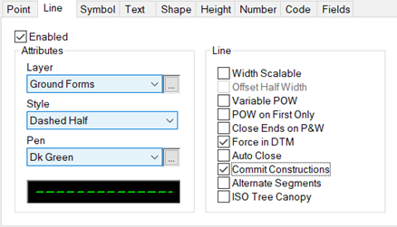
Defining Code Table Line Feature Commitment
In the case of O= and W=, the lines and points will have the same height as the point that they were surveyed from. There is a special option when using P= for parallels, to generate height difference from the base string. (see below).
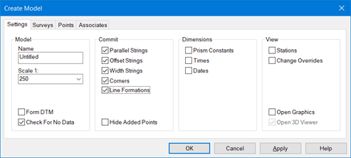
Creating a New Model with Committed Features
Note: The code table and model create buttons must be checked for these additional line features to be committed.
Parallel Line Feature Options
Parallel line features can be created in several ways. Here we will look at directly from coding.
A Dimension P=<attributes> to the first or last point in a line feature, will create a parallel phantom line. The sign convention is right +ve and left –ve, from the first point on the feature.
Using P=Offset,Code,dh will add a second line with a different code and height difference, when committed.

Parallel Offset Using P= Dimension
Further parallel line options are available when editing your survey, and can be found in the Lines menu shown below. The All, Between and Thru Points options take an existing string feature and are used in conjunction with a Parallel String dialog, shown below, to identify the code and reference height of new points on the parallel string.
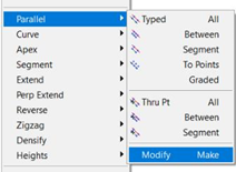
Parallel Line Menu Options (Pro & Designer)
The Graded option is useful when setting out batter slope rails and to calculate the levels along a string off a design line. A perpendicular line is generated off the design line through another string, until it hits a third string (setting out) and a point is created along this grade.
The To Points option is used to generate a parallel string feature from individual points, as opposed to a whole feature used in other options in this menu.
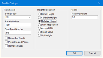
Creating Points on a Parallel Feature
A special parallel option, called Make, allows you to force a near parallel feature to have a fixed offset to another string. For example, a channel line feature being made fixed offset to a top of kerb feature. The levels of points along the feature being moved are retained.

Moving Features Parallel – Before

Moving Features Parallel - After
The ends of the second string MUST lie within the extents of the reference string. The first point on the string to be made parallel, is initially projected to the reference string and the perpendicular offset calculated. This offset is then applied to all other points to be moved.
Corners in Features using Comma Codes
Six new Comma Codes have been introduced to help with building surveys. They all involve the creation of corners in line features and can be added when querying a point.

Query Point Dialog With Comma Code Corner Options

Corner Comma Codes
The K Comma Code uses a sequence of four points to merge into a corner and must appear on the fourth point. It will take the lines created by the first and second points and intersect it with the line between the third and fourth, to form the corner.
The L and M Comma Codes allow you to create corners. This may be where a chimney breast is being surveyed and one of the corners is not visible. Each option uses a sequence of four points to create the corner and the comma code must appear on the fourth point
The H and J Comma Codes allow you to create perpendicular corners on leading and training legs of a polyline, made up from four points.
The O Comma Code is used to create a parallel offset line through this point. Five points are required.
When creating a model from a survey, the option to “Commit” these new corner points as real points in the model, is available in a similar way to that for committing width, parallel and offset features. Levels for these “new” points will be interpolated between points either side.
Note: Incorrect results will be obtained if you use the parallel, offset or width dimensions with these comma codes, as the parallels will be calculated without the virtual points. If you “Commit” these features when creating a model, then the resulting parallels will be correct as the additional points will have been included in the feature.
Extending Lines Using X=
The Dimension X= can be used to extend a line at the end of a segment (also internally). This option only works with observations during reductions and can be used in situations where a point is obscured, like the corner of a building, by vegetation. The level of the extended point is taken from the previous point.

Extending Lines
Line Formations
There are situations where survey detail needs to be identified using taped measurements, especially where sightings are blind. The Dimension L= is used here with paired numbers; the first number identifying the line orientation and the second, its length. Pairs are separated by spaces, commas, a slash or hash character. For example, LF=0,4.5/-2,1.5/2,2.5/2,1.5. This works along a line segment as shown here.

Using the LF= Dimension
ISO Tree Canopies
For surveys that need to identify tree canopies more accurately, ISO Tree Canopies can be used. This involves recording the spread from the centre of the tree in four directions. These are measured in direction of the four compass points N, E, S & W. The Dimension TC= is used with comma delimited measurements. In the example shown below, TC=3.5,4.5,5.6,7.0.
The ISO Tree Canopy option needs to be checked in the Lines tab of the Code Table for the tree code being used.

ISO Tree Canopy
Feature Reporting
A feature reporting option has been added to the Tools Menu in the Observations and Co-ordinate graphics views, called Report Codes, and Features menu in the Model graphics view, called Report. This option allows you to generate a report of the feature codes used in a survey or model and identifies undefined codes. Selecting the option will cause a dialog box similar to that shown below to be displayed.
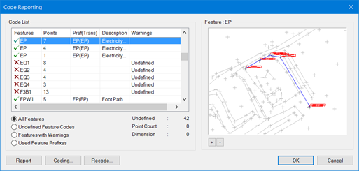
New Feature Reporting Option
Initially, the control contains a list of all the features that are in the survey or model. The content of the list control is governed by the group of radio buttons underneath with four options.
All Features will display all of the features in a survey or model
Undefined Feature Codes will only display features where the feature code is not recognised from the list of defined code prefixes
Features with Warnings will display undefined feature codes together with features where the number of points is incompatible with the generation of multi-point shapes and symbols or a dimension is missing from a point
Used Feature Prefixes will display all the feature prefixes that have been recognised
When displaying a feature, a green tick signifies that its code has been recognised and that there are no problems with the point count, whilst a red cross indicates otherwise. Other information is displayed, such as the number of points in the feature and some details about the prefix that has been recognised. Highlighting a feature in the list control causes the graphic view to the right to be updated showing where the feature is. Double-clicking on the list control will bring up the Query Feature Dialog Box for the highlighted feature.
When displaying the prefixes used, the number of features that use that prefix, together with some details of the prefix, are displayed in the list control. In this case, the graphic view contains an indication of the position of all the features using the highlighted prefix.
The Report button will generate a text report of the contents of the list control. The Coding button allows you to change the settings for the prefix used in the highlighted feature or prefix. If the code is missing from the Code Table, this option allows you to define a new code. The Recode button allows you to recode a feature and is only available in the Model View. The + & – buttons allow you to zoom in and out of the graphics window.
Any changes you make to the feature codes will only be saved when you select the OK button to leave the dialog. If you have made changes to the code prefix table, however, these changes will always be retained in the current Project.


Comments
0 comments
Please sign in to leave a comment.