
There are several line styles that are used to display lines on either the computer screen or a printer. They are all user-definable and are stored in a windows configuration file called LSTYLES.INI. Currently, you must change the contents of this file to define new line styles or alter existing ones. Therefore, the dialog box used for line style settings is for viewing line styles only and is a property sheet dialog consisting of a series of property pages, one for each type of line style.
It is often the case that you have no wish to load all the line styles that are available. For all but the simple line styles, there are check boxes in the dialog list controls that allow you do this.
Simple Line Styles
These lines are formed by a simple pattern that is repeated along the direction of drawing. The simple line styles property page is shown below.
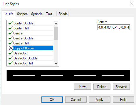
The numbers represent the lengths of lines and gaps which are in millimetres at the final print. If a number positive, then a segment is drawn whilst if a number is negative, a gap is left. A number of 0.0 represents a dot. When drawing a multi-segment line, the pattern is continued through each apex and not restarted for each segment.
The simple line styles are stored in their own section in the configuration file, a part of which is shown below.
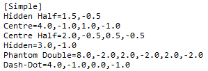
Each line style occupies its own line in this section and simply contains the on-off pattern. To define a new line simple line style, insert a new line in the configuration file and enter the required name and pattern.
Shape, Text and Symbol Line Styles
These line styles are more complex in that, as well as the on-off pattern, you have the option to draw a given shape, piece of text or symbol within the line. The shapes line style property page is shown below and those for text and symbol line styles are broadly similar.
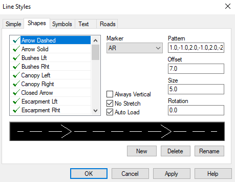
The additional column defines the marker that is to be used in the line style. These markers are stored in a configuration file called MARKERS.INI. They are user-definable if you understand how AutoCAD shape files work but normally, AiC can create any new markers that you require. A shape line style has its own section inline styles configuration file and an example is given below.
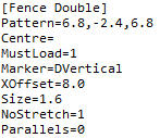
The section name defines the name of the line style and the keys within the section define the various parameters for the line style as follows.
- Pattern: Defines the pattern repeat the linear line segments. You would normally allow for a central gap into which the marker shape will be placed when drawing.
- Marker: Defines the name of the marker that will be inserted into the line style.
- XOffset: Defines the offset along the line style at which the marker will be inserted. This will normally be half the total length of the line pattern
- Size: Is the scale that is applied to the marker. It is assumed that the marker has been created at a size equivalent to 1mm.
- NoStretch: specifies whether the marker is to be stretched to fit into a line segment. When drawing complex lines, n4ce will scale the line pattern to fit between tow line apexes. If this value is set to 0, the central gap and marker will be stretched as well. If this is set to 1, the central gap and the marker will not be stretched.
- Parallels: For future use
- Always Vertical: The orientation of the shape can only be vertical no matter the direction of the string.
- AutoLoad: The Shape will automatically load into the current project.
For symbol line styles, the Marker line in the configuration file should be replaced by a Symbol line which defines the name of the symbol to be inserted. It is up to you to ensure that the symbol is loaded into the current project.
For text line styles, the Marker line in the configuration file should be replaced by a String line which defines both the string to be displayed and the text style to be used. These items need to be comma-separated by a comma.
Road Marking Line Styles
The final type of line style allows you to create road markings as a series of polygons. The length, spacing and width of road markings for specific situations are specified by the Highways Agency and the available line styles represent those that are required. The road marking line styles property page is shown below.
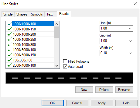
The columns of the list control define the line style name, the length of, the gap between and the width of the white lines.
Like the simple line styles, the road marking line styles are stored in their own section in the configuration file and a part of this section is show below.
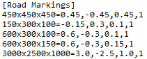
The patterns in these line styles need to be generated at the correct size, whatever the scale. Therefore, you are expected to define them in metres rather than millimetres. The three numbers are the length of each line element, the gap between the elements and the width of each element. Note that the gap between each line follows the general convention and should be negative. When road marking lines are exported to an AutoCAD DXF file, they are exported as a series of polygons since AutoCAD cannot accurately reproduce them.
The tick box in the bottom right Road Markings as Solid Lines fills the road markings so that they appear solid, rather then just outline line work.
Comments
0 comments
Please sign in to leave a comment.