
In rural areas, electricity and telephone wires are often suspended overhead from wooden poles. To create a graphic representation of this, you could use a line to represent the overhead wire and a single point circle to represent each pole. An item of feature text next to each pole will signify what the wires are for.
You will not always be able to survey these points at ground level so they can be used in a ground model and a reading is taken further up the pole. In this case, you should consider using the option not to model points in the Point property page. If you do not use this option, you may have to add the comma code to exclude the required points from the model.
 |
 |
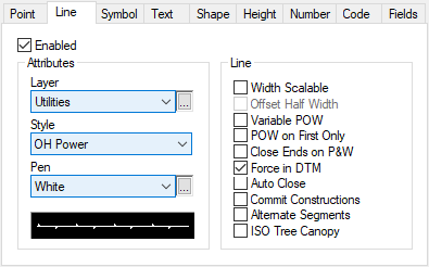
In the Line property page, you can set the required line style. For overhead wires, there is a line style called OH Power which is designed for this situation. In this example, none of the check boxes in the Attributes Group should be checked. These may adversely affect the display of the feature but also the formation of the triangles.
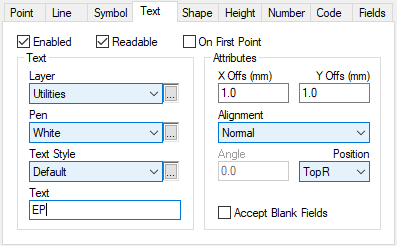
The Text property page can be set to display a text string next to each pole. For instance, you could use EP if you are surveying electricity wires or TP if you are surveying telephone wires.
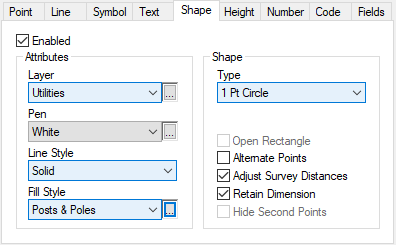
The Shape property page should be set to display one of the single point circles. Because electricity and telegraph poles tend to be the same size, a default value for the radius, diameter or circumference should be set up in the Fields property page. You can use the option that will adjust the surveyed distances by the radius of the pole so that you do not need to provide the distance offset dimension. Some clients will prefer a post to be shaded so use a fill style using the solid fill pattern with the required colour. In this case, you should consider using the point style called None.
Comments
0 comments
Please sign in to leave a comment.