Various options are available for converting the coordinates of Stations, Points or Models into a new coordinate system.
- Simple 2D Translation and Rotation based on two points
- 2D Least Squares Helmet based on two plus points
- Full 3D Least Squares transformations (Pro&Des)
- A temporary transformation is also available in models called, called Elevations (Pro&Des)
In general, transformations can take place from either the control grid (spreadsheet) or in the graphics environments.

Transformations using a Control Grid
It’s important here to identify the points being used in the transformation. In the spreadsheet they are highlighted, which in graphics they must be selected. A large cross will then appear on the selected points. Double selection removes them.

Transformations in Graphics
Make sure you can identify points/stations in your survey and have the new coordinates of these points/stations available.
At the end of the transformation process you will be invited to save the transformation so that it can be applied to other data folders, including Coordinates Models, Stations and CAD. This option can be found in the Tools menu in CAD, or the right click menus in control grids and Points --> Transfer in model graphics.

Applying Transformations – Selection of Previously Saved
Simple 2D Transformation
This is carried out by identifying 2 points/stations in a data folder or graphics (model) and is particularly useful if you want to rotate your survey and are not worried about the resulting coordinate system.

Simple 2D Transformation
If you are using the control grid (Stations, Co-ordinates or Model) highlight 2 points from the grid first, then right click over the highlight and select Transfer --> Create 2D.
Alternatively, if you are carrying out the transfer in model graphics, first select Points --> Transfer Points 2D option followed by identifying the two points you wish to use in the transfer.

2 Point Transformation
The two points that were selected appear in the dialog together with their name and current coordinates. You are expected to enter the new coordinate values in the windows provided. If you simply wish to rotate your survey horizontally, based on the selected points, simply copy the northings value into the opposing window, so they are the same. Unless the Centre Origin is checked, the survey will rotate about the new first point coordinates.
If Apply Scale is checked, then the survey will scale about the selected new points coordinates. It’s also possible to Load previously recorded coordinates that are saved in a Co-ordinates folder, provided the names are the same.
The 2 Point Transformation dialog is the same for both graphics and control grid.
2D Helmert Transformation
A greater level of control is provided by using this option as you can force or float the scale and is particularly useful when tying into the OS Nation Grid coordinate system and GPS control. The only different between the simple transformation and this is that you pick more than two points for the transformation. This gives you redundancy, so a least squares technique is used to find a solution.
An indication of the goodness of fit is provided through the Standard Error. The transformation is updated automatically as you enter new coordinates and its also possible to Load previously recorded coordinates stored in a Co-ordinate folder.

Multi Point 2D Helmet Transformation
New East/North coordinates can be typed in for each point or loaded from a pre-recorded coordinate folder. In the latter the codes and numbers must be the same as the ones they are changing. The Transformation Parameters will be updated automatically as you enter new coordinate values. The standard error here is 0.008710, which is less than 1cm. The scale has been allowed to float and is 0.999575.
ticked points indicates live points that will be used in calculations, whilst crossed points will be ignored. Double click on these lines to add/remove points from consideration. An error report can be generated with the results of calculations.
CO-ORDINATE TRANSFORMATION
==========================
SELECTED POINTS
===============
Original New
Code Number Easting Northing Easting Northing
------------------------------------------------------------------------
STN3 609.3299 356.3629 1609.3000 2356.3630
STN8 499.0578 362.9738 1499.0580 2362.9740
STN1A 577.6037 572.3006 1577.6040 2572.2010
------------------------------------------------------------------------
TRANSFORMED POINTS
==================
Transformed
Code Number Easting Northing dX dY
------------------------------------------------------------------------
STN3 1609.2923 2356.3564 -0.0077 -0.0066
STN8 1499.0677 2362.9760 0.0097 0.0020
STN1A 1577.6020 2572.2056 -0.0020 0.0046
------------------------------------------------------------------------
LEAST SQUARES PARAMETERS
========================
Method : Helmert
Standard Error : 0.00871042
Origin-E (m) : 1561.9873
Origin-N (m) : 2430.5127
Translation-E (m) : 999.9902
Translation-N (m) : 1999.9669
Rotation : 359°59'39"
Scale : 0.99957514
The equation being solved looks like this:
X = λ*[x*COS(Φ) + y*SIN(Φ)] + dx
Y = λ*[x*SIN(Φ) – y*COS(Φ)] + dy
Where X & Y are the new coordinates and x & y are the current coordinates of points.
dx and dy are the translations, λ scale and Φ is the rotation.
In both the Grid and Graphics methods, selecting OK will apply the transformation to all the points in that folder. You will be invited to save the transformation parameter so they can be applied to other data folders.
Note: For the Helmet Transformation to work selected points must not lie on a straight line. It’s also advisable to select points for the transformation from the extreme extents of your survey as any error will magnify away from the selected points,
3D Transformations (Pro & Designer)
These can only be accessed from the graphics environment and are used with a minimum of 5 points. Again, select the option first and then select 5+ points graphically. The Load option is also available here.

Using Points for Transformation on the List
If you add points to a List first then use the List Pick option, you use these points and the maybe load option to repeat the process very easily.
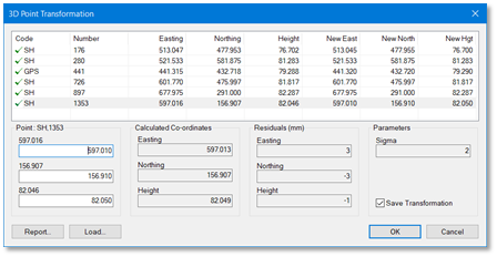
3D Transformation Parameters
In this case all three XYZ new coordinates need to be entered alongside the existing coordinates. The arrow indicates which points are used in calculations. Double click to add/remove points just like in the 2D case.
One extra feature shown here are the Residuals, or goodness of fit, for each individual point in terms of X, Y & Z. These are calculated from the new parameters using a scale, three rotations and three translations (dx, dy & dz) to calculate new coordinates and taking these away from typed in new XYZ values.
The Sigma value is the overall goodness of fit, calculated by squaring and summing the individual residuals then taking the average.
3D CO-ORDINATE TRANSFORMATION
=============================
SELECTED POINTS
===============
Original New
Code Number Easting Northing Height Easting Northing Height
--------------------------------------------------------------------------------------------------
SH 176 513.0474 477.9534 76.7023 513.0450 477.9550 76.7000
SH 280 521.5328 581.8745 81.2828 521.5328 581.8745 81.2828
GPS 441 441.3152 432.7179 79.2879 441.3200 432.7200 79.2900
SH 726 601.7702 475.9974 81.8169 601.7702 475.9974 81.8169
SH 897 677.9753 290.9998 82.2869 677.9753 290.9998 82.2869
SH 1353 597.0162 156.9066 82.0462 597.0100 156.9100 82.0500
--------------------------------------------------------------------------------------------------
TRANSFORMED POINTS
==================
Transformed Residuals
Code Number Easting Northing Height dX dY dZ
--------------------------------------------------------------------------------------------------
SH 176 513.0476 477.9550 76.7025 0.0026 0.0000 0.0025
SH 280 521.5342 581.8762 81.2816 0.0014 0.0016 -0.0012
GPS 441 441.3149 432.7204 79.2895 -0.0051 0.0004 -0.0005
SH 726 601.7704 475.9981 81.8161 0.0002 0.0007 -0.0008
SH 897 677.9735 290.9997 82.2875 -0.0019 -0.0001 0.0006
SH 1353 597.0129 156.9074 82.0494 0.0029 -0.0026 -0.0006
--------------------------------------------------------------------------------------------------
Sigma = 3.31663mm
Note: the selected points must not fall on a single line or plane.
Scale
This option allows you to apply a scale to points in graphics, either All or by Pick Mode. Points will be scaled radially about this origin, including detail in the dedicated CAD backcloth. The sample below was scaled to 0.5.
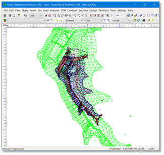
Centred Scaled – shown as a Backcloth in Green
Elevations (Pro & Designer)
Whilst it would be a useful feature to be able to rotate your survey in real time and carry your edits, this is not currently available (but on a wish list for future development). The nearest tool we have to this is available in our 3D viewer, where you can digitise data, but not edit strings directly.
So, we’ve built in a tool into the modeller that allows you to flip the model onto a different face, edit in this view, then flip it back to the original plan view swapping the Y and Z axes. The is the normal way of viewing elevations, but we’ve added the reverse option.
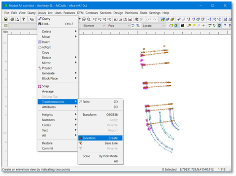
Building Survey – Viewed in Plan
The first stage is to identify points that can be used to flip the view about. The Create option request the two points whilst the Base Line option request a feature segment.
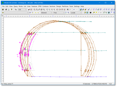
Transformed Elevation Image
Remember you are editing in an elevation so Z values are now Y values and visa versa. This feature is only available in the n4ce Professional & Designer editions. When you Reverse, the model returns back to its original orientation. Any detail in the dedicated CAD backcloth is not transformed.
For those using our Lite edition there are tools for generating elevations. This is done by defining two points which represent a baseline. The survey will be rotated to this baseline before swapping the Y and Z axis, but there is no reverse option. Another option would be to simply sway the Y & Z axis in the control grid, as shown below.

Swapping Coordinates
If you are presenting height text on an elevation as part of the finished drawing remember that this is now the Y coordinate. Use the Text macro %PY% to display levels.
OSGB36 Transformations
This option can be used to transform a model from OSTN02 to OSTN15 or from OSTN15 to OSTN02 coordinate systems. The Current System will be displayed. In the case shown below its Unknown and you will be expected to know which one applies and apply the correct transformation. Clearly we need to be working in OS national Grid coordinates.
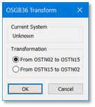
OSGB36 Transformations

Comments
0 comments
Please sign in to leave a comment.