
Both triangle and grid models can be viewed in 3D using the 3D Model Viewer. This can be accessed when you are viewing a model graphically by using a button on the standard toolbar, a yellow cube, or by using the 3D Model option which can be found at the bottom of the View menu. ![]() When this option is accessed, a new window like that shown below will be displayed. Note the old 3D Viewer can still be accessed by holding Shift and the 3D Cube icon is clicked.
When this option is accessed, a new window like that shown below will be displayed. Note the old 3D Viewer can still be accessed by holding Shift and the 3D Cube icon is clicked.
The main view in the window shows you the current 3D view in which you are able to use the mouse to spin the model to any view that is required. Initially, the view on the model will be vertically down onto the centre of the model extents.
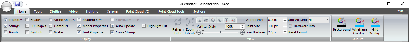
Across the top is a ribbon bar which contains all the commands necessary to control the data that is displayed in the 3D view.
To the left is a property window which enables you to change the display settings for each model that is currently being viewed. When you initially view a model in 3D, n4ce will also view any models in its backcloth and each of the models that are displayed will have its own set of display settings in this property window.
Controlling the 3D View
The Centre of Vision is the location about which you can rotate the current view in 3D and is represented by an object comprising of three perpendicular lines of different colours. The blue line is used to indicate the direction of the Z-axis, up and down, the green line is used to indicate the Y-axis, north and south, and the red line is used to indicate the X-axis, east and west. When the left mouse button is down and you move the mouse, the view will rotate about the centre of vision. You can also use the mouse wheel to zoom in and out on this point.
If you hold the Ctrl key down and click the left button on the mouse, the centre of vision will be moved to the position of the mouse cursor. Since the centre of vision always remains in the centre of the 3D view, a pan will take place and the image in the view will adjust accordingly. The new centre of vision will be calculated where the direction of view intersects with the model being viewed. This option is repeated by the Set Centre button which can be found on the Tools Panel.
If you hold the right mouse button down and move the mouse, this enables you to raise or lower the height of the centre of vision. If you hold the mouse wheel down and move the mouse, this enables you to manually drag the model around the view updating the centre of vision as you go.
Note that it is possible for the centre of vision to be below the model. In this case, it may not be visible when using solid displays. Also, if you continuously zoom in, you will get to a point where the eye point and centre of vision become very close to each other and little change will be noticed. If you wish to zoom in further, you must change the centre of vision.
Comments
0 comments
Please sign in to leave a comment.