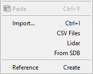
Right clicking the Models folder in the project manager displays the following menu. This is the gateway to much of the functionality within n4ce and as such is worth taking time to fully familiarise yourself with. The following document is split into a series of sections.

- New Normal: Starts the process of adding a new Survey Model to the project.

The create dialog is split into four sections- Model
- Name: Assigns a suitable name to the new Model
- Scale: Sets the default view scale to be used when displaying the model graphically.
- Form DTM: Creates the ground model at the same time the new model is added to the project.
- Check For No Data: This check box signals n4ce to alert the user if they press Ok to create the model before adding any Survey or Point data to it.
- Commit: Generates new feature strings from Parallel, Offset, Width, Corners and Chain Offset attributes attached to linear objects. Enables physical 3d points to be generated where as there would otherwise be 2d linework which is not editable as normal survey detail would be.
- Hide Added Points: Gives the new detail added by the commit option a series of comma codes that hide the points and annotation.
- Dimensions:
- Prism Constants: Carries any prism constants forward into the model from a reduced survey.
- Times: If the information is available this option carries the time of day forward into the model from a reduced survey as an attribute.
- Dates: If the information is available this option carries the date forward into the model from a reduced survey as an attribute.
- View:
- Stations: Enable the view of stations behind the model.
- Change Overrides: Display the layer override dialog before the model is displayed. Useful when modelling large datasets to turn off height annotation for example if it may slow the display down.
- Open Graphics: Open the graphics view onto the model automatically.
- Open 3D Viewer: Opens the 3D View automatically. Only available if the 2D graphics window is also enabled.
- Model
- New Copy: Creates a new model by entirely duplicating an existing project.
- New Isopachyte: Starts the process of generating a height difference model between two others. Usually a design and a original ground model. Points will have a positive height where the Base surface is above the Projection.

- Simple Projection: For very large datasets this will result in faster processing, but will be less accurate. Instead of subdividing crossing triangles and projecting from the projection surface back to the Base, the calculation is purely Base to projection.
- Group Depths: Take into account any groups in the BASE model with depths attached to them.
- Double Group Depths: Take any groups with depths, in either the Base or Projection models into account.
- New Point Grid: Generates a new model which contains a regular grid of points with a code, at a given spacing, interpolated over the source models DTM surface.

- Gradient and Direction: Assign gradient and direction attributes to each point. Useful for generating plans of golf greens.
- Group Depths: Take group depths in the source model into account when interpolating the height of the points in the grid.
- Group Names: Attach to each point the name of any group it falls inside in the source model.
- New Lidar Grid: Creates a real time fixed grid model over a selected survey model. In much the same way as a point grid is generated the spacing must be specified.

For very large models the "Number of Spacings" field can be used to subdivide the grid into smaller tiles. Where each tile edge has this number of cells. - New Merge: Takes a design or similar Foreground model and inserts it into a Background model. Where the two surfaces overlap the foreground model takes precedence over the background model. The triangles around the edge of the foreground model are stitched into the surrounding background model and any points within that boundary in the background model are deleted before the foreground is inserted into it.

- New Combine: Adds multiple models together, but does not cut the DTM surfaces into each other. Useful when multiple people have been editing a long road or rail survey and have worked on different parts. The individual edited sections can then be combined with this tool.
- Perp Offset: Creates a new model where the triangles are offset perpendicular to the surface of the original, rather than just vertically. Used to model clay liners for landfill sites.
- Borehole: Uses the contents of a specially formatted CSV file to generate multiple models based on the locations and depths to different strata recorded in the file.

- Group Formation: Generates a new model by taking all the triangles from a given model and lowering them vertically by their group depths (if they have them). If adjacent groups have different depths, then vertical gaps will occur in the model.

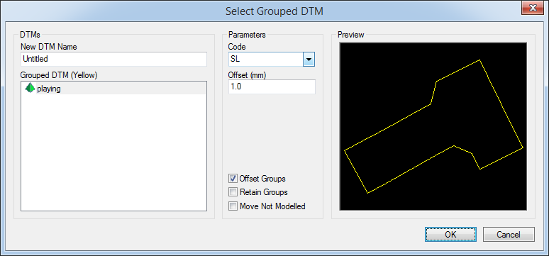
- Offset Groups: Where two or more groups meet with different depths, then new offset points are created on the interface between the various groups to help create the necessary steps. The Code and Offset distances are controlled via the boxes provided. The resulting model will probably need some manual editing because the new points and strings can form quite complex geometry. If the triangles can not be verified then a warning message will pop up and the suspect points added to the List.
- Retain Groups: Preserves the grouping, i.e. this groups the new surfaces with the original groups that defined them.
- Move Not Modelled:
- Single: This again creates a new model, lowered by the group depths. But for only a single model.

- From AutoCAD File: Extracts the Triangles and or Polyface Mesh from a DWG or DXF file and generates a new model with the same surface triangles. If duplicate meshes are found in the source file, then multiple models will be created to hold each individual surface.
- From OS Heights: imports the ground model from OS .GML files.
- From MX DTM: Extracts the DTM from MX GENIO files (if the DTM data is present). Sometimes these are provided as .TXT files. If so then the files first need to be renamed to .GEN before they will be recognised properly.
- From Grid File: This option reads text files containing a series of gridded XYZ coordinates aligned to north, and converts it into a Lidar grid DTM. Normally this data comes as .ASC files, but sometimes it is also provided as a simple series of coordinates.

- Paste: Assuming a model has been placed on the clipboard whist a second n4ce Project is open at the same time. Paste will transfer it the current project. This is the simplest and easiest way to copy data between projects. For very large models, the From SDB option will be faster.
- Import (From File): Loads raw point data from a given file. If using GNSS or you are happy that the coordinates calculated by the survey instrument are correct, then the raw data can be loaded straight into a model, bypassing the Observations and Coordinates folders altogether.
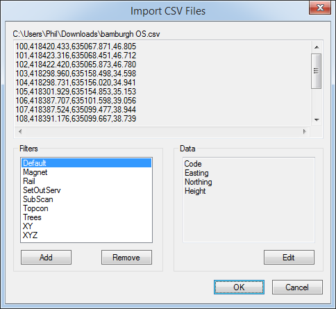
- Import CSV Files: Loads raw point data from CSV files. The format of the data needs to be predefined so that n4ce knows what type of data is in each column. Having selected the file a dialog box similar to that below will be shown.

The data is previewed in the top of the dialog, whilst and predefined filters are shown below and the order that they expect information to be in.
To edit or otherwise setup a new filter press Edit when the appropriate filter is highlighted.
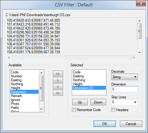
Configuring a CSV filter is straight forward. Simply select the data item from the Available list and use the > button to move it over to the selected column. Once in the selected column it can be moved up and down in order or altered further to set its data type. For Dimensions, these can be moved over as many times as is necessary. Its just the Dimension identifier which is changed each time. So any data in the 5th field above will come in and be added to the attributes column in the model as S=<some data>.
- Remember Code: Is used to remember the Code from the previous reading(s) if it is missing.
- Headers: Adds the names of the columns to the top of the CSV when exported.
- Skip Lines: Set to 1 of the imported file has a single line at the top describing the column names. Or larger if there is a large header block at the top of the file.
- Import Lidar: Reads .ASC files and generates realtime grid DTMs. See here for more info.
- Import From SDB: Extracts models which exist in a given SDB file and copies its data into the current project.
- Reference Create: This option loads the model from another SDB file into the current project but as a shallow reference. This means that the actual data for the model still resides in the second SDB file. As and when the referenced model is needed for the likes of sections and volumes, the file is opened and the model data loaded into memory. This allows large OGL surveys for instance to still be used and accessed, but without bloating project files that may contain designs, and don't necessarily need the OGL data all the time.

Comments
0 comments
Please sign in to leave a comment.